Continue to Site

Welcome to EDAboard.com

Welcome to our site! EDAboard.com is an international Electronics Discussion Forum focused on EDA software, circuits, schematics, books, theory, papers, asic, pld, 8051, DSP, Network, RF, Analog Design, PCB, Service Manuals... and a whole lot more! To participate you need to register. Registration is free. Click here to register now.

limit the current load

Status
Not open for further replies.

canarybird33

Member level 1
Member level 1
Joined
Apr 16, 2013
Messages
41
Helped
2
Reputation
4
Reaction score
2
Trophy points
1,288
Location
Mashhad, Iran, Iran
Visit site
Activity points
1,591
hello
I want to limit the current load at 300 mA and turn the LED on.
I don't know how choose R5 to bias the transistorQ2 and Q4.
I just know in 300 mA Q4 should be turned on(to cause the base current of Q2 be limited).
V=R4(3.3 ohm)*Iload(300mA) should turn the Q4 on.

but the circuit doesn't work correctly.
What's the problem?
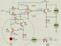
 
Last edited by a moderator:

hello
I want to limit the current load at 300 mA and turn the LED on.
I don't know how choose R5 to bias the transistorQ2 and Q4.
I just know in 300 mA Q4 should be turned on(to cause the base current of Q2 be limited).
V=R4(3.3 ohm)*Iload(300mA) should turn the Q4 on.

but the circuit doesn't work correctly.
What's the problem?

<a title="5.JPG" href="http://obrazki.elektroda.pl/6033278900_1406026854.jpg"><img src="http://obrazki.elektroda.pl/6033278900_1406026854_thumb.jpg" alt="5.JPG" /></a>
Hi canarybird33
Unfortunately i can't see your attachment , can you re attach it or perhaps upload it somewhere else ?

Best Luck
Goldsmith
 

The schematic has a yuck background color covered with a grid. It is here:
 

Attachments

  • limit the load current.png
    limit the load current.png
    395.3 KB · Views: 87
The schematic has a yuck background color covered with a grid. It is here:
Hi Audioguru
Thanks buddy ! :smile:

Hi again canarybird33
Now , in order to answer the question ,
May i ask you a question , why you don't do it more simpler ? why not just a simple programmable current source ? or even a current mirror !


Best Wishes
Goldsmith
 

I think the problem is this: with 300 mA flowing through R4, the voltage at that point will be 1V. Assuming the LED has a forward voltage of say, 2V, the transistor will be off.

The current required to start to turn the transistor on will be Vbe(.6V) + Vled(2V)/3.3=787mA.
 

Your LED is in wrong place for constant current. It needs to be in the collector of the transistor on the right. Also the 2N3904 has a max. current of 200mA. You need a higher current transistor such as a 2N2222.

Below is a simulation of the corrected circuit. I tweaked the resistor values to get 300mA current.

If you need to operate with the LED grounded then you would use PNP transistors.

Constant Current.gif
 
why you don't do it more simpler ? why not just a simple programmable current source ? or even a current mirror !

Hi Goldsmith
There is a load which sink 4mA to 300mA
I want design a circuit to convert this current to voltage(0 to 5) beside a limiting current protector to protect the LOAD
do you have any other idea to detect the short circuit fault and protect the LOAD?
 

I think the OP is looking for a current LIMITER, NOT a current SOURCE.

With that said, canarybird, why do you have an LED in the emitter of your over-current detector? The circuit is almost right, but, as I said in post 5, the LED is messing up your circuit.
 

why do you have an LED in the emitter of your over-current detector? The circuit is almost right, but, as I said in post 5, the LED is messing up your circuit.

I removed the LED.Now which pin can help notify the over current to a microcontroller?.


I can't understand what is exactly happening when I change R5.the circuit doesn't work properly.
I chose R1=3.3 ohm to make 1volt to turn Q4 on and limit Q2's current.but it doesn't work.
R4 (as Rsens) is Series with R(load)==> isn't make any problem for turning

- - - Updated - - -

If all you need is a current limiter then just use the circuit I show in post #6.

The circuit limit LOAD current But I think it doesn't work as I expect.I simulated the circuit as you have designed(I removed LED in my circuit and changed transistor to 2N2222) BUT: increasing load current causes increasing Base current of Q2 and increasing collector current of Q4 !!!!! (I expect that: Increasing the current load should causes decreasing Base current of Q2 and turning Q4 on )[in my design]

Let me know how did you choose the R=499 ?
 

The circuit limiter I posted allows any current up to the limit value. Are you talking about a fold-back limit whose current goes down with a short circuit? You seem to be going through a lot of hoops just to limit current. :???:

The increasing collector current in Q4 with increasing load is correct since Q4 is starting to starve the base current to Q2 which limits its output current.

The 499Ω value of R2 is somewhat arbitrary. It just has to supply adequate base current to Q1 for the maximum load current with the minimum supply voltage.
 
Hi Goldsmith
There is a load which sink 4mA to 300mA
I want design a circuit to convert this current to voltage(0 to 5) beside a limiting current protector to protect the LOAD
do you have any other idea to detect the short circuit fault and protect the LOAD?
Hi again
Sorry because i'm late , i know this topic marked as solved but i though it might be helpful .
Yes of course . you could use a simple hiccup current limiter as well . i guess you're familiar with that ?


Best Wishes
Goldsmith
 

Status
Not open for further replies.

Part and Inventory Search

Welcome to EDABoard.com

Sponsor

Back
Top