Continue to Site

Welcome to EDAboard.com

Welcome to our site! EDAboard.com is an international Electronics Discussion Forum focused on EDA software, circuits, schematics, books, theory, papers, asic, pld, 8051, DSP, Network, RF, Analog Design, PCB, Service Manuals... and a whole lot more! To participate you need to register. Registration is free. Click here to register now.

LEM LV 25-P output drive

Status
Not open for further replies.

VirusX2

Member level 4
Joined
Nov 18, 2014
Messages
77
Helped
1
Reputation
2
Reaction score
0
Trophy points
1,286
Activity points
1,849
Hi all, i have a LEM voltage transducer (LV 25-P). As the datasheet says the maximum measuring resistor is 190 or 350 ohm according to the measuring range and supply. I want to drive the output with a current to voltage op-amp so i convert the LEM's output into voltage and offset it by 2.5V. If i use the measuring resistor topology i need an 82 ohm resistor. So if i use a current to voltage op-amp can the circuit on the image work?

circuit.jpg
 

The circuit doesn't work with most general purpose OPs because the transducer current (up to +/-50 mA peak) exceeds the available OP output current. A passive shunt with resistor voltage divider respectively level shifter is simpler and better.
 

The circuit doesn't work with most general purpose OPs because the transducer current (up to +/-50 mA peak) exceeds the available OP output current. A passive shunt with resistor voltage divider respectively level shifter is simpler and better.

I am using the AD817 op-amp, the datasheet says 50mA Minimum output current, so i suppose this op amp can drive the lem's output.

Am i wrong?
 

Won't consider AD817 as general purpose OP. Like other high bandwidth OPs, it has larger output current. But the OP would get quite hot.

Still think that a passive resistor circuit is preferable.
 
Won't consider AD817 as general purpose OP. Like other high bandwidth OPs, it has larger output current. But the OP would get quite hot.

Still think that a passive resistor circuit is preferable.

An Rsense with a difference amplifier may be better?
 

way better.

Use the manufacturer's recommended burden resistance and then amplify it with a good opamp
 
Is this circuit better to get an output with 2.5V reference? The burden the LEM will see is only the 82 ohm resistor, right?

Cir.jpg
 

A differential amplifier would be needed if the current measurement shunt has separate sense connections, or the shunt ground and signal ground have a voltage difference for any other reason. A simple single OP differential amplifier is the most simple solution.

In your circuit, the large AD817 input bias current will ruin accuracy with 100k resistors. The resistor value are O.K. for general purpose OPs, AD817 should use e.g. 1k.

If shunt ground and signal ground are the same, a simple resistor circuit can be used instead of an OP, see post #2.
 

Hi,

I often use a circuit like in post#7.
Especially with low ohmic shunts (milliohms) one can improve precision by wiring the "sense" traces directely to the shunt pads.

If you see high frequency noise at the output, then adding a capacitor across R1 may improve on this. Depending on noise source an additional capacitor across R4 may be a further improvement.
****
About the bias current. I don't see this that critical. The resistance at both inputs is the same therefore the bias current error should fairly good be canceled out. But offset current may introduce errors. If you have a better Opamp by hand then replace the AD817.

Klaus
 

I tested the circuit on post #7 and worked quite well. I also have in mind something like the circuit attached below. Is is better than the deferential amp for this purpose?

cir2.jpg
 

    V

    Points: 2
    Helpful Answer Positive Rating
Hi,

I don´t see a benefit in the circuit of post#11

****

If you use an ADC, then don´t use two references --> use only one reference. This is cheaper and more precise.

Klaus
 

Hi,

I don´t see a benefit in the circuit of post#11

****

If you use an ADC, then don´t use two references --> use only one reference. This is cheaper and more precise.

Klaus

What do you mean about the references? I use the MCP1525's 2.5V as reference for the signal. Do you mean that the reference here must be the same as the ADC reference?
 

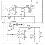
Everybody has its own favorite circuit. Mine is shown below, which I've successfully used for many, many years.

I've shown low cost LM358 opamps, you can use premium or rail-to-rail opamps for increased accuracy and/or range.

The key here, is that many microcontroller ADCs are ratiometric to the supply voltage. In this instance, one does not require a precision reference but rather only split the supply in half, buffer it and then use that as a "virtual ground".

Capture.PNG
 
Everybody has its own favorite circuit. Mine is shown below, which I've successfully used for many, many years.

I've shown low cost LM358 opamps, you can use premium or rail-to-rail opamps for increased accuracy and/or range.

The key here, is that many microcontroller ADCs are ratiometric to the supply voltage. In this instance, one does not require a precision reference but rather only split the supply in half, buffer it and then use that as a "virtual ground".

View attachment 128369

Thank you very much for the circuit

Will your circuit work if i replace the LM358 with AD817?
 

Hi,

Do you mean that the reference here must be the same as the ADC reference?

Yes, use the same reference_IC. But if you need you need a different reference_voltage then generate it ... maybe by using resistive divider.

Often one uses ADC_Ref = 5V (reference IC) for biasing the input you need VRef/2 tehn use the 5V and a resistive divider to get 2.5V
In the circuit of post#7 instead of 100k to 2.5V_Ref I recommend to use one 200k to 0V and one 200k to 5V_ADC_Ref.

More precision:
If you use two references: then if the 5V reference drifts this causes a DC offset in ADC_reading. If the 2.5V referece drifts this too causes a DC offset in ADC reading.

If you use one reference: then a drift of VRef does not cause a DC offset in ADC reading.

Klaus
 
Status
Not open for further replies.

Similar threads

Part and Inventory Search

Welcome to EDABoard.com

Sponsor

Back
Top