Continue to Site

Welcome to EDAboard.com

Welcome to our site! EDAboard.com is an international Electronics Discussion Forum focused on EDA software, circuits, schematics, books, theory, papers, asic, pld, 8051, DSP, Network, RF, Analog Design, PCB, Service Manuals... and a whole lot more! To participate you need to register. Registration is free. Click here to register now.

[SOLVED] LED blinking using TIP127

Status
Not open for further replies.

venkates2218

Full Member level 6
Joined
Sep 30, 2016
Messages
354
Helped
1
Reputation
2
Reaction score
1
Trophy points
1,298
Activity points
4,306
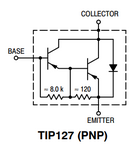
Please refer the image,TIP127 is interfaced with PIC18F4520 to control an LED.The objective is LED have to blink,but LED connected at output of TIP127 is always in ON condition.
While checking MCU pin with another LED,it blinking as like program.Input to TIP127 is +12VDC.

How to solve this issue with TIP127.?
 

Attachments

  • tip127.jpg
    tip127.jpg
    46.7 KB · Views: 119

Hi,

About your picture: why doesn't it use the standard bjt symbol. There's a good reason why they exist: it's readable all over the world.
Your show a physical pin arrangement which is for PCB, not for schematic.

You talk about transistor "input" and "output". But a bjt does not have dedicated input and output. Thus please use: emitter, collector, base .... and it's clear all over the world what you mean.

Did you read basic bjt function explanation? Do this.
A bjt becomes conductive depending on V_be. It is about 0.6V for a standard bjt and about 1.2V for a darlington. Negative values fir PNP.
Below 0.6V (1.2V) the bjt becomes high ohmic, above 0.6V it becomes conductive.

Please estimate your V_be (including resistor) when:
* port = HIGH
* port = LOW

Do you see what happens?

Klaus
 

Simple LED drive circuit looks like -

1599557730933.png


Note in case of NPN add a 10 -25K R to output pin to ground to keep
LED off when micro starts up, as typically micro puts its pin into Hi Z
on startup and leakage of NPN could turn it on, especially in elevated
T environments. Do same for PNP but R goes from pin to Micro Vdd
supply pin.

In either case the R in series with LED limits current when on, calculated
as Rled = (Vsupply - Vcesat- Vled) / Iledmax. Of course you worst case
the various V's in the expression to insure you do not exceed Iledmax
you desire. That includes T effects.

The R in series with transistor base, desired base current is Iled / 10,
that insure transistor saturates, turns on hard. You can write the KVL
equations to calculate it.

If your Iledmax is >> 10's of mA then you need to consider thermal effects
on transistor, its Pdissipation and possible need for heat sink.....Web has
many apnotes on calculating max junction temp and heat sink size and its
thermal resistance.


Regards, Dana.
 
Last edited:

Your schematic shows no LED and shows no current limiting resistor for it.
You use a 12V supply for the TIP127 PNP darlington but the input from your PIC microcontroller does not go high enough (to about +11V or +12V) to turn off the darlington.

Why didn't you copy the symbol of the TIP127 from its datasheet like this?
 

Attachments

  • TIP127.png
    TIP127.png
    13.2 KB · Views: 73

Status
Not open for further replies.

Similar threads

Part and Inventory Search

Welcome to EDABoard.com

Sponsor

Back
Top