Vermes
Advanced Member level 4
Main task of the system is to detect presence of people in a room by lighting up LED strips which illuminate the ceiling (7 meters of white strip 2700K). Clicking the switch enables additional lighting in the form of halogen lamps for 230V – it is 12x 50W bulbs.
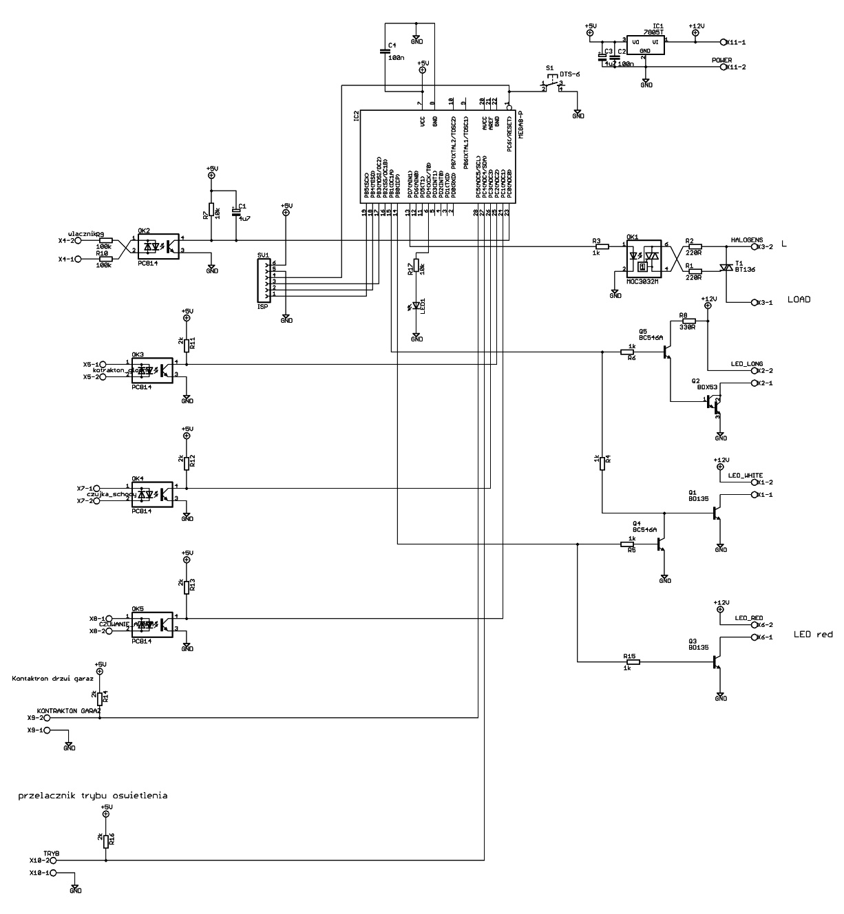
The main element that controlls the whole device is AVR processor Atmega8. It works without a quartz – it is set on internal resonator 4MHz. Connectors of ISP programmer were derived next to the processor.
Power:
The board should be supplied from a 12V voltage source with a capacity of at least 3-4A. The driver has 5V stabilizer with a filter in the form of capacitors 47uF and 2x 100nF.
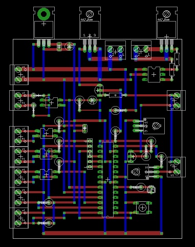
PCB:
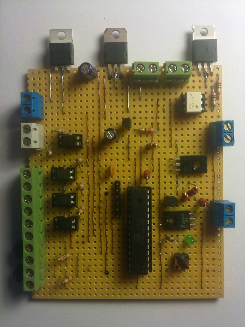
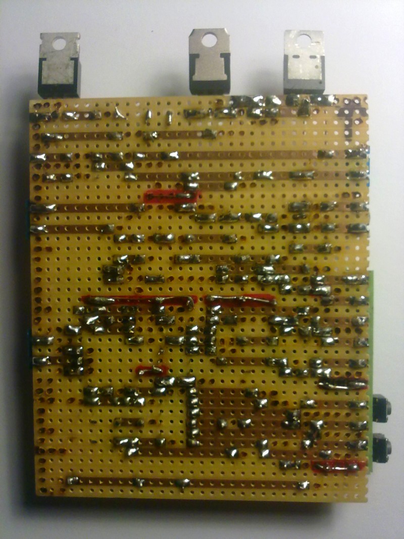
The PCB was made on VERO-board.
Inputs:
A signal from the switch connected to the driver forces the galvanic isolation. That is why optotransistor PC814 was used in series with two resistors 100kohm. At the optotransistor output there is a buffer in the form of RC elements – so at the optotransistor output there will be no 100Hz rectangular signal.
The driver has also three isolated inputs that allow you to connect to three signal from alarm panel, so the system will know if somebody enters the room from one or another side. Two inputs are subsumed to the supply „plus” - one for connecting the reed switch, another to connect the switch used for selecting the driver operation mode.
Outputs:
Driver output 230V is isolated by galvanic optotriac – it controls the triac BT136-600E. That output is used to control the halogen lighting.
The system has three outputs for LED stripes – one output of high and two of low power. Executive element of the high power output to control the LEDs is transistor BDX53C, while for the low power outputs there are two transistors BD135. One of them controlls a segment of 7m, 2 and 3 – segments of 0,5m each. LED strips consume 0,4A per meter.
2 and 3 output for LEDs are dependent from each other – enabling the 3 output causes negation of the 2 output, which in turn is enabled when the 1 output is enabled. Enabling both outputs 1 and 3 in one time causes turning off the 2 output.
Software:
The program was written in C. It takes about 4,5kB. LEDs are controlled from PWM output – OC1A. While turning on the light, LEDs light up smoothly. During turning off, the brightness also dims gradually. PWM was set to 8-bit resolution. It operates in FASTPWM mode, so you do not need to corrent the phase.
The system has a button that resets the processor and LED connected to the PD.4 output – as a control.
Pictures:
Schematic diagram:
PCB:
Link to original thread (useful attachment) – Sterownik oświetlenia LED oraz halogenowego w pomieszczeniu by Narasta
 ,
,