Continue to Site

Welcome to EDAboard.com

Welcome to our site! EDAboard.com is an international Electronics Discussion Forum focused on EDA software, circuits, schematics, books, theory, papers, asic, pld, 8051, DSP, Network, RF, Analog Design, PCB, Service Manuals... and a whole lot more! To participate you need to register. Registration is free. Click here to register now.

Lead Acid backup battery charging and switching.

Status
Not open for further replies.

Astrid

Full Member level 3
Full Member level 3
Joined
Jul 11, 2011
Messages
152
Helped
4
Reputation
8
Reaction score
3
Trophy points
1,298
Visit site
Activity points
2,492
Need in case of power failure (AC) power to automatically attach the backup battery (12V Lead Acid 7-30Ah) current 2.5A max. It is probably not a problem P-MOSFET + diode.
But I would like the device to recharge the battery and watched her status with regard to maximum durability and energy savings.
For charging a 14V +, but sometimes that can be 17V +.
The devices have a processor, looking for some inspiration for the scheme, or suitable circuit for supervision
 

It sounds as though you have a 12V power supply. It provides power continually to some device. Is this correct?

So suppose you were to hook up to the battery in the middle. You regulate the power supply to 13.8 V (a normal constant condition for a 12V battery). Perhaps as low as 12.8 V.

The battery would trickle charge, yet not overcharge. Its power would be available immediately if there is a blackout.
 

Describe those going slightly more accurately
Power is
either AC 16V => DC 17V
or
switching power supply DC 13.8V max 2.5A
device is 7/24
If the power fails I want to add a backup battery 12V 4-30 Ah
I like taking the battery attached so as not to constantly recharged, because it costs money and, second, shorter battery life.
Therefore, we need either a controllable current source 0-1A
or switched current source, for example, 0, 100 mA, 700 mA (not charging, slow and fast charging)
 

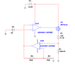
For example
R1 current shunt resistor
U2A amplifi voltage on R1 Vout= R1*I* (1+R3/R2)=R1*I*10
U2 drive PMOSFET Q1 so that V3=10*R1*I for V3=2V I over R1=2A
In real V3 is DAC
During power failure (V1 = 0) the device is powered from batterie across the diode in Q1.
ADA4661 not completely cheap amp, but need to find a cheaper precise Rail to Rial Amp.
What do you think?
CS.png
 
  • Like
Reactions: Astrid

    Astrid

    Points: 2
    Helpful Answer Positive Rating
Status
Not open for further replies.

Similar threads

Part and Inventory Search

Welcome to EDABoard.com

Sponsor

Back
Top