Continue to Site

Welcome to EDAboard.com

Welcome to our site! EDAboard.com is an international Electronics Discussion Forum focused on EDA software, circuits, schematics, books, theory, papers, asic, pld, 8051, DSP, Network, RF, Analog Design, PCB, Service Manuals... and a whole lot more! To participate you need to register. Registration is free. Click here to register now.

[SOLVED] LCD Software Help PIC 16F877A

Status
Not open for further replies.

oiyela

Junior Member level 3
Joined
Mar 7, 2012
Messages
30
Helped
0
Reputation
0
Reaction score
0
Trophy points
1,286
Activity points
1,554
Hi,
I am currently doing my project and i need to test my microcontroller with an LCD screen, i am using HI-tech compiler on mp lab. my code builds but does not display anything or put on the LCD. Please Help
Here is what i mapped the microcontroller pins to


Code C - [expand]
1
2
3
4
5
6
7
8
9
10
11
12
13
14
15
16
17
18
19
20
21
22
23
24
25
26
27
28
29
30
31
32
33
34
35
36
37
38
39
40
41
42
43
44
45
46
47
48
49
50
51
52
53
54
55
56
57
58
59
60
61
62
63
64
65
66
67
68
69
70
71
72
73
74
75
76
77
78
79
80
81
82
83
84
85
86
87
88
89
90
91
92
93
94
95
96
97
98
99
100
101
102
103
104
105
106
107
108
109
110
111
RD4 to LCD_RS
RD5 to LCD_EN
 
RD0 to LCD_D4
RD1 to LCD_D5
RD2 to LCD_D6
RD3 to LCD_D7
 
Here is my software:
 
#ifndef _XTAL_FREQ
 // Unless specified elsewhere, 4MHz system frequency is assumed
 #define _XTAL_FREQ 8000000
#endif
 
#include    <htc.h>
#include    "lcd.h"
 
#define LCD_RS RD4
#define LCD_EN RD5
 
#define LCD_DATA    PORTD
 
#define LCD_STROBE()    ((LCD_EN = 1),(LCD_EN=0))
 
/* write a byte to the LCD in 4 bit mode */
 
void
lcd_write(unsigned char c)
{
    __delay_us(40);
    LCD_DATA = ( ( c >> 4 ) & 0x0F );
    LCD_STROBE();
    LCD_DATA = ( c & 0x0F );
    LCD_STROBE();
}
 
/*
 *  Clear and home the LCD
 */
 
void
lcd_clear(void)
{
    LCD_RS = 0;
    lcd_write(0x1);
    __delay_ms(2);
}
 
/* write a string of chars to the LCD */
 
void
lcd_puts(const char * s)
{
    LCD_RS = 1; // write characters
    while(*s)
        lcd_write(*s++);
}
 
/* write one character to the LCD */
 
void
lcd_putch(char c)
{
    LCD_RS = 1; // write characters
    lcd_write( c );
}
 
 
/*
 * Go to the specified position
 */
 
void
lcd_goto(unsigned char pos)
{
    LCD_RS = 0;
    lcd_write(0x80+pos);
}
    
/* initialise the LCD - put into 4 bit mode */
void
lcd_init()
{
    char init_value;


    init_value = 0x3;
    TRISA=0;
    TRISD=0;
    LCD_RS = 0;
    LCD_EN = 0;
    
    
    __delay_ms(15); // wait 15mSec after power applied,
    LCD_DATA     = init_value;
    LCD_STROBE();
    __delay_ms(5);
    LCD_STROBE();
    __delay_us(200);
    LCD_STROBE();
    __delay_us(200);
    LCD_DATA = 2;   // Four bit mode
    LCD_STROBE();
 
    lcd_write(0x28); // Set interface length
    lcd_write(0xF); // Display On, Cursor On, Cursor Blink
    lcd_clear();    // Clear screen
    lcd_write(0x6); // Set entry Mode
}

 
Last edited by a moderator:

hi
why you are not mention lcd READ/WRITE pin your program ?
are you connect lcd read/write pin in your microcontroller?
check your circuit and write coding like RD6 to LCD_RW
 

i connected Read/Write To Ground. So It Stays Low
 

read your lcd header file and also read inside lcd_write function

---------- Post added at 13:50 ---------- Previous post was at 13:45 ----------

lcd read write pin is important to display what u like to display so connect ur lcd read/write pin to ur micro controller i/o pin & mention that i/0 pin in your codings like this #define LCD_EN RD5
 

The Code Builds Without Any Error So The Header Files And Declarations Are Okay. I Just Think Am Missing Out Something Out In The Code
 

lcd read write pin is important to display what u like to display in your coding.send ur circuit diagram
 

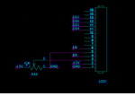
The direction of data transfer is controlled by the R/W pin. If it is pulled Low, the commands or character data is written to the LCD module. And, when it is pulled high, the character data or status information from the LCD registers is read. Here, we will use one way data transfer, i.e., from microcontroller to LCD module, so the R/W pin will be grounded permanently. i have attached a picture of my LCD circuit LCD CIRCUIT.png
 

its correct lcd read write pin takes low means write data to lcd.high means read data.your circuit connected to low signal.so lcd write data continiously.when the pin is set to high means its display ur codings data.
 

Status
Not open for further replies.

Similar threads

Part and Inventory Search

Welcome to EDABoard.com

Sponsor

Back
Top