Luis Daniel Bolaños
Member level 2

- Joined
- Apr 4, 2014
- Messages
- 47
- Helped
- 2
- Reputation
- 4
- Reaction score
- 2
- Trophy points
- 8
- Activity points
- 342
Hi everybody!
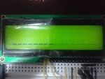
I'm working on the PIC16F887 trying to make a temperature sensor using LM35 and displaying temperature on LCD 16x2. In the beginning I used 7 segments and it worked fine. Then, I copied some code I found online for LCD and it works on proteus simulation. However, when using hardware the LCD just shows some random pixels on... Here is the code I use just for the display
On the configuration bits I turned OFF the WDT and LVP bits. What else can I try? What am I doing wrong?
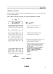
In proteus I use the LM016L LCD 16x2 display. My LCD is the SSC2B16DLYY, and the datasheet is **broken link removed**
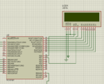
The connection I'm using on ISIS and breadboard is the following

I'm working on the PIC16F887 trying to make a temperature sensor using LM35 and displaying temperature on LCD 16x2. In the beginning I used 7 segments and it worked fine. Then, I copied some code I found online for LCD and it works on proteus simulation. However, when using hardware the LCD just shows some random pixels on... Here is the code I use just for the display
Code:
VISUALIZAR
START_LCD
        call INICIA_LCD   ;LCD Configuration
        call M1           ;First message
        call LINEA2       ;Second line configuration
        call M2           ;Second message
        goto CONVERSION

;Mensaje a enviar
M1
        movlw ' '
		movwf PORTC
		call ENVIA
        movlw ' '
		movwf PORTC
		call ENVIA
        movlw 'T'       ;Mueve 'H' a W
		movwf PORTC       ;PORTC = W
		call ENVIA        ;Prints on LCD
		movlw 'e'
		movwf PORTC
		call ENVIA
		movlw 'm'
		movwf PORTC
		call ENVIA
		movlw 'p'
		movwf PORTC
		call ENVIA
		movlw 'e'
		movwf PORTC
		call ENVIA
        movlw 'r'
		movwf PORTC
		call ENVIA
		movlw 'a'
		movwf PORTC
		call ENVIA
		movlw 't'
		movwf PORTC
		call ENVIA
		movlw 'u'
		movwf PORTC
		call ENVIA
        movlw 'r'
		movwf PORTC
		call ENVIA
        movlw 'a'
		movwf PORTC
		call ENVIA
        movlw ':'
		movwf PORTC
		call ENVIA
        return
M2
        movf TMP3, W
        call DECO_LCD
		movwf PORTC
		call ENVIA
        movf TMP2, W
        call DECO_LCD
		movwf PORTC
		call ENVIA
		movf TMP1, W
        call DECO_LCD
		movwf PORTC
		call ENVIA
        movlw '°'
		movwf PORTC
		call ENVIA
        movlw 'C'
		movwf PORTC
		call ENVIA
        movlw ' '
		movwf PORTC
		call ENVIA
		movlw 'N'
		movwf PORTC
		call ENVIA
		movlw 'i'
		movwf PORTC
		call ENVIA
		movlw 'v'
		movwf PORTC
		call ENVIA
        movlw 'e'
		movwf PORTC
		call ENVIA
        movlw 'l'
		movwf PORTC
		call ENVIA
        movlw ':'
		movwf PORTC
		call ENVIA
        movlw ' '
		movwf PORTC
		call ENVIA
        btfss PORTE,0
        goto no
        movlw 'X'
        goto send
no      movlw 'O'
send    movwf PORTC
		call ENVIA
        return

;Subrutina para inicializar el lcd
INICIA_LCD
        bcf PORTD,0      ; RS=0 Instruction mode
        movlw 0x01		 ; Clear screen
		movwf PORTC
		call COMANDO     ; Se da de alta el comando
		movlw 0x0C       ; Selecciona la primera línea
		movwf PORTC
		call COMANDO     ; Se da de alta el comando
		movlw 0x3C       ; Se configura el cursor
		movwf PORTC
		call COMANDO     ; Se da de alta el comando
		bsf PORTD, 0     ; Rs=1 Data mode
        return

;Subrutina para enviar comandos
COMANDO
        bsf PORTD,1	    ; Pone la ENABLE en 1
        call demora      ; Tiempo de espera
        bcf PORTD, 1    ; ENABLE=0
		call demora
		return

;Subrutina para enviar un dato
ENVIA
		bsf PORTD,0     ; RS=1 MODO DATO
		call COMANDO    ; Se da de alta el comando
		return
;Configuración Lineal 2 LCD
LINEA2
       	bcf PORTD, 0    ; RS=0 MODO INSTRUCCION
        movlw 0xc0		; Selecciona linea 2 pantalla en el LCD
		movwf PORTC
		call COMANDO    ; Se da de alta el comando
        return

DECO_LCD        addwf PCL, F
                retlw b'00110000'
                retlw b'00110001'
                retlw b'00110010'
                retlw b'00110011'
                retlw b'00110100'
                retlw b'00110101'
                retlw b'00110110'
                retlw b'00110111'
                retlw b'00111000'
                retlw b'00111001'
                retlw b'00110000'
                retlw b'00110000'
On the configuration bits I turned OFF the WDT and LVP bits. What else can I try? What am I doing wrong?
In proteus I use the LM016L LCD 16x2 display. My LCD is the SSC2B16DLYY, and the datasheet is **broken link removed**
The connection I'm using on ISIS and breadboard is the following


