Continue to Site

Welcome to EDAboard.com

Welcome to our site! EDAboard.com is an international Electronics Discussion Forum focused on EDA software, circuits, schematics, books, theory, papers, asic, pld, 8051, DSP, Network, RF, Analog Design, PCB, Service Manuals... and a whole lot more! To participate you need to register. Registration is free. Click here to register now.

[SOLVED] LCD interfacing with PIC18F452

Status
Not open for further replies.

syeda amna

Full Member level 4
Full Member level 4
Joined
Jun 1, 2010
Messages
222
Helped
24
Reputation
48
Reaction score
22
Trophy points
1,308
Location
Pakistan
basicelectronicsguide.blogspot.com
Activity points
2,551
I want to interface 16x2 LCD with PIC 18F452. I am using CCS compiler and Proteus 7.8. What is wrong?
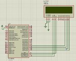
LCD.JPG
My C code is here

Code:
#include <18F452.h>                   
#use delay (clock=4000000) 
#define LCD_ENABLE_PIN  PIN_E0                                   
#define LCD_RS_PIN      PIN_E1                                     
#define LCD_RW_PIN      PIN_E2                                   
#define LCD_DATA4       PIN_D4                                     
#define LCD_DATA5       PIN_D5                                     
#define LCD_DATA6       PIN_D6                                     
#define LCD_DATA7       PIN_D7 
#include <lcd.c>                   
#fuses HS,NOWDT,NOPROTECT,NOLVP 
 
void main()
{
   set_tris_d(0x00); 
   set_tris_e(0x00);
   lcd_gotoxy(1,1);
   lcd_init(); 
   Delay_ms(1000); 
   printf(lcd_putc,"Hello");

}
 

include the fuses in the 2nd line of your program. you must include before #use delay line.

use as .
#include <18F452.h>
#fuses HS,NOWDT,NOPROTECT,NOLVP
#use delay (clock=4000000)

Best wishes :)

- - - Updated - - -

Also you must initialize your lcd first. In your main program you are displaying the string Hello for 1 time.
change as,
HTML:
void main()
{
   set_tris_d(0x00); 
   set_tris_e(0x00);
   lcd_init(); 
   lcd_gotoxy(1,1);
   Delay_ms(1000); 
   printf(lcd_putc,"Hello");   // displays only one time "Hello" in the LCD. 

}
 
In your proteus simulation, you didn't connect crystal to OSC1 and OSC2.
Looking into your datasheet, you could not use internal oscillator.

So please connect the crystal at the corresponding pins and load the hex. It will work.

use
HTML:
#fuses XT
 

I want to interface 16x2 LCD with PIC 18F452. I am using CCS compiler and Proteus 7.8. What is wrong?
View attachment 84605
My C code is here

Code:
#include <18F452.h>                   
#use delay (clock=4000000) 
#define LCD_ENABLE_PIN  PIN_E0                                   
#define LCD_RS_PIN      PIN_E1                                     
#define LCD_RW_PIN      PIN_E2                                   
#define LCD_DATA4       PIN_D4                                     
#define LCD_DATA5       PIN_D5                                     
#define LCD_DATA6       PIN_D6                                     
#define LCD_DATA7       PIN_D7 
#include <lcd.c>                   
#fuses HS,NOWDT,NOPROTECT,NOLVP 
 
void main()
{
   set_tris_d(0x00); 
   set_tris_e(0x00);
   lcd_gotoxy(1,1);
   lcd_init(); 
   Delay_ms(1000); 
   printf(lcd_putc,"Hello");

}


I think the connection is not complete. Please try this connection, D0,D1,D2,D3,RW and VSS should be connected to ground. RS, E, D4, D5, D6, D7 is the only pins connected to the microcontroller. VDD is connected to source. You may not connect VEE to source or ground.

Code:
#include <18F452.h>                   
#use delay (clock=4000000)                                  
#define LCD_RS_PIN      PIN_E1                                     
#define LCD_RW_PIN      PIN_E2                                   
#define LCD_DATA4       PIN_D4                                     
#define LCD_DATA5       PIN_D5                                     
#define LCD_DATA6       PIN_D6                                     
#define LCD_DATA7       PIN_D7 
#include <lcd.c>                   
#fuses HS,NOWDT,NOPROTECT,NOLVP 

void main()                //  you should initialize the LCD before doing any commands
{
   lcd_init(); 
   set_tris_d(0x00); 
   set_tris_e(0x00);
   lcd_gotoxy(1,1);
   Delay_ms(1000); 
   printf(lcd_putc,"Hello");

}
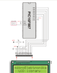
Hope this helps.
 
Last edited by a moderator:

Can you check if the lcd.c that you are using has its own pin definitions?
If so you will have to change the pins there.


If this does not work, try flex_lcd.c
picmania.garcia-cuervo.net/recursos/flex_lcd.c

This also requires you to change the pin definitions in the header file itself.
 
The file is in the directory where you installed the CCS compiler. I think its in the folder called 'Drivers'. Just do a search for it.

Open the lcd.c file in a text editor, and make the changes and save it.

I have felt that the 'flex_lcd.c' driver is better.
To use that, just save this file in the folder where you found the lcd.c file.
 
Please connect the oscillator 4MHZ across pin 13 and pin 14 with 22pF capacitors.
use this code
HTML:
#include "18F452.h"
#fuses XT                           
#use delay(clock=4000000)        // 4Mhz

#include <flex_for_test_lcd.c>               // lcd driver

void main()
{
output_low(PIN_E2);                          
lcd_init();                                     // lcd initialization
delay_ms(50); 
lcd_gotoxy(1,1);
delay_ms(10);
while(1)
{
lcd_putc("\f");
lcd_putc("Hellow");
delay_ms(1000);
}
}

and also save this driver where you have installed the ccs software under the drivers folder.
HTML:
// Flex_lcd_16x1.c 

// These are randomly assigned pins, used to test 
// that the driver can work with any arrangement 
// of i/o pins.  
#define LCD_DB4   PIN_D4 
#define LCD_DB5   PIN_D5 
#define LCD_DB6   PIN_D6 
#define LCD_DB7   PIN_D7 

#define LCD_RS    PIN_E1 
//#define LCD_RW    PIN_E2
#define LCD_E     PIN_E0

/* 
#define LCD_DB4   PIN_D4 
#define LCD_DB5   PIN_D5 
#define LCD_DB6   PIN_D6 
#define LCD_DB7   PIN_D7 

#define LCD_RS    PIN_E0 
#define LCD_RW    PIN_E1 
#define LCD_E     PIN_E2 
*/ 

// If you want to use a 6-pin interface for your LCD, then 
// connect the R/W pin on the LCD to ground and comment 
// out the following line.  A 6-pin interface to the LCD 
// is used if only have a few free i/o pins available on 
// your PIC, and you want to use the smallest possible 
// number of pins for the LCD. 
//#define USE_LCD_RW   1        

//======================================== 
// Use "2 lines" as the lcd type for the 16x1 LCD. 
// The LCD is the same as an 8x2 LCD, but with the 
// bottom line appended on the right side of the first line. 
#define LCD_TYPE  2         // 0=5x7, 1=5x10, 2=2 lines 
#define LCD_2ND_HALF_ADDRESS  0x40 

#define LCD_WIDTH  16 
#define LCD_HALF_WIDTH  (LCD_WIDTH/2) 

int8 const LCD_INIT_STRING[4] = 
{ 
 0x20 | (LCD_TYPE << 2), // Func set: 4-bit, 2 lines, 5x8 dots 
 0xc,                    // Display on 
 1,                      // Clear display 
 6                       // Increment cursor 
 }; 

int8 lcd_xcoord; 
                              

//------------------------------------- 
void lcd_send_nibble(int8 nibble) 
{ 
// Note:  !! converts an integer expression 
// to a boolean (1 or 0). 
 output_bit(LCD_DB4, !!(nibble & 1)); 
 output_bit(LCD_DB5, !!(nibble & 2));  
 output_bit(LCD_DB6, !!(nibble & 4));    
 output_bit(LCD_DB7, !!(nibble & 8));    

 delay_cycles(1); 
 output_high(LCD_E); 
 delay_us(2); 
 output_low(LCD_E); 
} 

//----------------------------------- 
// This sub-routine is only called by lcd_read_byte(). 
// It's not a stand-alone routine.  For example, the 
// R/W signal is set high by lcd_read_byte() before 
// this routine is called.      

#ifdef USE_LCD_RW 
int8 lcd_read_nibble(void) 
{ 
int8 retval; 
// Create bit variables so that we can easily set 
// individual bits in the retval variable. 
#bit retval_0 = retval.0 
#bit retval_1 = retval.1 
#bit retval_2 = retval.2 
#bit retval_3 = retval.3 

retval = 0; 
    
output_high(LCD_E); 
delay_us(1); 

retval_0 = input(LCD_DB4); 
retval_1 = input(LCD_DB5); 
retval_2 = input(LCD_DB6); 
retval_3 = input(LCD_DB7); 
  
output_low(LCD_E); 
delay_us(1);  
    
return(retval);    
}    
#endif 

//--------------------------------------- 
// Read a byte from the LCD and return it. 

#ifdef USE_LCD_RW 
int8 lcd_read_byte(void) 
{ 
int8 low; 
int8 high; 

output_high(LCD_RW); 
delay_cycles(1); 

high = lcd_read_nibble(); 

low = lcd_read_nibble(); 

return((high << 4) | low); 
} 
#endif 

//---------------------------------------- 
// Send a byte to the LCD. 
void lcd_send_byte(int8 address, int8 n) 
{ 
output_low(LCD_RS); 

#ifdef USE_LCD_RW 
while(bit_test(lcd_read_byte(), 7)) ; 
#else 
delay_us(60);  
#endif 

if(address) 
   output_high(LCD_RS); 
else 
   output_low(LCD_RS); 
      
 delay_cycles(1); 

#ifdef USE_LCD_RW 
output_low(LCD_RW); 
delay_cycles(1); 
#endif 

output_low(LCD_E); 

lcd_send_nibble(n >> 4); 
lcd_send_nibble(n & 0xf); 
} 

//---------------------------- 
void lcd_init(void) 
{ 
int8 i; 

output_low(LCD_RS); 

#ifdef USE_LCD_RW 
output_low(LCD_RW); 
#endif 

output_low(LCD_E); 

// Some LCDs require 15 ms minimum delay after 
// power-up.  Others require 30 ms.  I'm going 
// to set it to 35 ms, so it should work with 
// all of them. 
delay_ms(35);      

for(i=0 ;i < 3; i++) 
   { 
    lcd_send_nibble(0x03); 
    delay_ms(5); 
   } 

lcd_send_nibble(0x02); 

for(i=0; i < sizeof(LCD_INIT_STRING); i++) 
   { 
    lcd_send_byte(0, LCD_INIT_STRING[i]); 
    
    // If the R/W signal is not used, then 
    // the busy bit can't be polled.  One of 
    // the init commands takes longer than 
    // the hard-coded delay of 60 us, so in 
    // that case, lets just do a 5 ms delay 
    // after all four of them. 
    #ifndef USE_LCD_RW 
    delay_ms(5); 
    #endif 
   } 

lcd_xcoord = 1; 
} 

//---------------------------- 
// The x-coordinate can be 1 to 16. 
// The y coordinate is ignored.  
// This x,y interface is kept in order to be 
// consistent with other CCS LCD drivers. 
void lcd_gotoxy(int8 x, int8 y) 
{ 
int8 address; 

// Update the global x-coordinate variable with the 
// current x coordinate. 
lcd_xcoord = x; 

// Convert the x-coordinate from CCS format (1-16) to 
// the 0-15 format used by the LCD hardware. 
address = x - 1;  

// If the x-coordinate is within the 2nd half of the 
// LCD line, the address must be adjusted because 
// of the special architecture of the 8x2 LCD. 
if(address >= LCD_HALF_WIDTH)  
  {    
   address += (LCD_2ND_HALF_ADDRESS - LCD_HALF_WIDTH); 
  } 

lcd_send_byte(0, 0x80 | address); 
} 


//----------------------------- 
void lcd_putc(char c) 
{ 
 switch(c) 
   { 
    case '\f': 
      lcd_send_byte(0,1); 
      delay_ms(2); 
      lcd_xcoord = 1; 
      break; 
    
    case '\n': 
       lcd_gotoxy(1,1);  //  Goto start of line 1 
       break; 
    
    case '\b': 
       lcd_send_byte(0, 0x10); 
       lcd_xcoord--; 
       if(lcd_xcoord == LCD_HALF_WIDTH) 
          lcd_gotoxy(LCD_HALF_WIDTH, 1); 
       break; 
    
    default: 
       lcd_send_byte(1, c); 
       lcd_xcoord++; 
       if(lcd_xcoord == (LCD_HALF_WIDTH +1)) 
          lcd_gotoxy(LCD_HALF_WIDTH +1, 1); 
       break; 
   } 
} 

//------------------------------ 
#ifdef USE_LCD_RW 
char lcd_getc(int8 x, int8 y) 
{ 
char value; 

lcd_gotoxy(x,y); 

// Wait until busy flag is low. 
while(bit_test(lcd_read_byte(),7));  

output_high(LCD_RS); 
value = lcd_read_byte(); 
output_low(lcd_RS); 

return(value); 
} 
#endif

- - - Updated - - -

save the above driver as named "flex_for_test_lcd.c". If you save it in any other name, program will show error.
 

Attachments

  • lcd1.bmp
    2.3 MB · Views: 169
One issue you are experiencing is the inclusion of the lcd.c source file contains macro definitions (#define) which essential override any previous macro definitions (#define) with the same identifier.


Code:
#include <18F452.h>                   
#use delay (clock=4000000)                                  
#define LCD_RS_PIN      PIN_E1                                     
#define LCD_RW_PIN      PIN_E2                                   
#define LCD_DATA4       PIN_D4                                     
#define LCD_DATA5       PIN_D5                                     
#define LCD_DATA6       PIN_D6                                     
#define LCD_DATA7       PIN_D7 
#include <lcd.c>  [COLOR="#FF0000"]// Macro definitions in this file essentially override those #defines above     [/COLOR]            
#fuses HS,NOWDT,NOPROTECT,NOLVP 

void main()                //  you should initialize the LCD before doing any commands
{
   lcd_init(); 
   set_tris_d(0x00); 
   set_tris_e(0x00);
   lcd_gotoxy(1,1);
   Delay_ms(1000); 
   printf(lcd_putc,"Hello");

}

You could try moving:

Code:
#include <lcd.c>

before the macro definitions (#define) contained in the main.c file:

Code:
#include <18F452.h>                   
#use delay (clock=4000000)   

#include <lcd.c>  [COLOR="#FF0000"]// Move this compiler directive before the macro definitions [/COLOR]            
                               
#define LCD_RS_PIN      PIN_E1                                     
#define LCD_RW_PIN      PIN_E2                                   
#define LCD_DATA4       PIN_D4                                     
#define LCD_DATA5       PIN_D5                                     
#define LCD_DATA6       PIN_D6                                     
#define LCD_DATA7       PIN_D7 

#fuses HS,NOWDT,NOPROTECT,NOLVP 

void main()                //  you should initialize the LCD before doing any commands
{
   lcd_init(); 
   set_tris_d(0x00); 
   set_tris_e(0x00);
   lcd_gotoxy(1,1);
   Delay_ms(1000); 
   printf(lcd_putc,"Hello");

}

Of course the macro identifiers in your main.c must match those macro identifiers in the lcd.c file to properly override them.

When defining conflicting macro definitions, the last macro definition with a particular identifier essentially wins.

BigDog
 

did you test the code without using crystal in hardware?
if its working in hardware without using crystal, what fuses have you used in the program?
 
yes I tested. The final program is very simple.
LCD.JPG
Code:
#include <18F452.h>   
#use delay (clock=4000000) 
#include <flex_for_test_lcd.c>               // lcd driver
     
void main()
{ 
      output_low(PIN_E2);
      lcd_init();

      lcd_putc("\f");
      lcd_putc("Hello");   
}
 
Last edited:

hi amna .
I'm not asking about in proteus. Did you tried to test in hardware(which means tested in protoboard)?
If you have hardware setup, Please load the hex in microcontroller and check it without using the crystal and without adding fuses in the program. To my point, it should not work.
Because proteus has a feature called processor clock frequency which you can see in edit option of your microcontroller. You are setting the clock frequency with this option even though you didn't add the fuses in the program. So it is working in the proteus.
But during simulation in real hardware, it won't work out.

_______________________________
If i'm wrong, Please correct me .
 
Status
Not open for further replies.

Similar threads

Part and Inventory Search

Welcome to EDABoard.com

Sponsor

Back
Top