Continue to Site

Welcome to EDAboard.com

Welcome to our site! EDAboard.com is an international Electronics Discussion Forum focused on EDA software, circuits, schematics, books, theory, papers, asic, pld, 8051, DSP, Network, RF, Analog Design, PCB, Service Manuals... and a whole lot more! To participate you need to register. Registration is free. Click here to register now.

[SOLVED] LC network synthesis: Example and questions

Status
Not open for further replies.

niki

Member level 4
Joined
Feb 20, 2002
Messages
70
Helped
20
Reputation
40
Reaction score
20
Trophy points
1,288
Location
Switzerland
Activity points
418
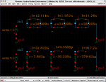
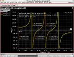
I placed a little LC-network example of synthesizing Driving-Point impedances with defined poles and zeros.
Two canonical realizations are shown. One of the networks have very exotic element values!!
Read the attachement and enjoy.
 

Attachments

  • Examples and questions related to one port reactance functions.pdf
    270.4 KB · Views: 82

See Analog and Digital Filters, Design and Realization", Harry Y.-F. Lam, (Prentice Hall, 1979). Chapter 5, Properties and Design of Lossless Driving-Point Functions.

As for the exotic component values, they are well in the range of usual SPICE simulators. Don't forget to reset default inductor series resistance to zero, if any.
 

If you drive circuits by ideal voltage source, simulator can not find DC operation point.
So drive circuits by ideal current source.

However if you use port as drive source, there should be no problem.
 
Last edited:

See Analog and Digital Filters, Design and Realization", Harry Y.-F. Lam, (Prentice Hall, 1979). Chapter 5, Properties and Design of Lossless Driving-Point Functions.

As for the exotic component values, they are well in the range of usual SPICE simulators. Don't forget to reset default inductor series resistance to zero, if any.

Attention: The problem is not as simple as it looks. For the second network the values are in the range
Capacitors:7.8e-9 ... 2.7
Inductors: 9.2e-16 ... 3.2e-8

I would be very surprised if a usual network simulator could analyze the network correctly.
Strange situation: normally the synthesis is more difficult than the analysis. but here the analysis is already a problem.
Again: How can you verify that the network is corrrect?
 

Loss of effective digits.

Build Z(s)=Num(s)/Den(s).
Then compare coefficients of polynomial.

I will use Control System Toolbox in MATLAB.
 
Last edited:

I would be very surprised if a usual network simulator could analyze the network correctly.
Strange situation: normally the synthesis is more difficult than the analysis. but here the analysis is already a problem.

Please check the Ltspice simulation.

SPICE simulator is generally using double precision for variables, apparently sufficient in this case. I know that you can design circuits that exceed the simulator's numerical dynamic.

Ltspice.png

Again: How can you verify that the network is correct?
I presume by calculating the poles and zeros. As for me, I'm contented to have the method described in the book, I'm not motivated to calculate it here and now.
 

Attachments

  • LC1.zip
    1.1 KB · Views: 81

- Can you show that the networks are equivalent?
From comparison of imag(Zin1) and imag(Zin2), we can say they are equivalent except for small numerical error.

However we can not realize this cauer expansion, since element values are not possible to realize.

- Can you analyze the second network with a simulation software?
(Please note the values of the elements)
See attached figure, there is no problem at all.
Here I used Synopsys HSPICE.

Attention: The problem is not as simple as it looks.
There is no problem at all.
And your issue is very simple just as it looks.

- Can you calculate the elements values of the following topology?
- How did I find the networks?
Your cauer expansion is a LPF type expansion.
However this topology requires a HPF type expansion of cauer expansion.
 

Attachments

  • 2017-1030-1006-36.png
    2017-1030-1006-36.png
    39.9 KB · Views: 119
  • 2017-1030-1026-55.png
    2017-1030-1026-55.png
    98.1 KB · Views: 132

Your cauer expansion is a LPF type expansion.
However this topology requires a HPF type expansion of cauer expansion.
As far as I see, both Cauer 1 (LPF) and Cauer 2 (HPF) can represent the original circuit.
 

The present network is similar to the Cauer 1 and Cauer 2 example 2 in the lecture with 2 capacitors and 2 inductors. You see that the same impedance function can be implemented both ways.
 

Please check the Ltspice simulation.

SPICE simulator is generally using double precision for variables, apparently sufficient in this case. I know that you can design circuits that exceed the simulator's numerical dynamic.

View attachment 142126


I presume by calculating the poles and zeros. As for me, I'm contented to have the method described in the book, I'm not motivated to calculate it here and now.

The present network is similar to the Cauer 1 and Cauer 2 example 2 in the lecture with 2 capacitors and 2 inductors. You see that the same impedance function can be implemented both ways.

Thank you for the Spice Simulation. Shame on me. I completely underestimated the power of LTSpice.
Well Done! Of course the equivalence of the circuit2 is shown.
From time to time, I will present further examples from network theory, which can not easily be solved with a tool.
Regards
Peter
 

Status
Not open for further replies.

Part and Inventory Search

Welcome to EDABoard.com

Sponsor

Back
Top