Continue to Site

Welcome to EDAboard.com

Welcome to our site! EDAboard.com is an international Electronics Discussion Forum focused on EDA software, circuits, schematics, books, theory, papers, asic, pld, 8051, DSP, Network, RF, Analog Design, PCB, Service Manuals... and a whole lot more! To participate you need to register. Registration is free. Click here to register now.

layout for antenna spatial diversity

Status
Not open for further replies.

biff44

Advanced Member level 6
Joined
Dec 24, 2004
Messages
5,047
Helped
1,376
Reputation
2,748
Reaction score
1,056
Trophy points
1,393
Location
New England, USA
Activity points
37,908
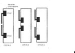
I thought I knew this stuff, but started to have some doubts. I have two receiver chips, and am going to attach a quarterwave monopole to each, in hopes of attaining some spatial diversity. 915 Mhz. I was going to use configuration A. My thinking was that the antenna phase center is where the monopole whip meets the ground plane, so configuration A gets the antenna phase centers the farthest apart. But then I looked at the antenna ends almost touching, and started to doubt my logic.

Which antenna orientation, printed on the same board area, would give me the greatest spatial diversity: A, B, or C? And why?
 

Attachments

  • Graphic3.jpg
    Graphic3.jpg
    37.6 KB · Views: 117

The two antenna should be as afr as possible, since it's spatial diversity. It's should be 4~5 wavelengths apart, but maybe it's impossible for your system.
Is it possible for changing config A two antenna perpendicular to the board, that's the farest.
 

If you can not get spacing then polarization diversity may provide the most benefit.

All your drawings have strong coupling between antenna's. Right angles for polarization diversity also provide some isolation between antennas. In office or residential environment there will be a lot of reflections that get cross polarized making polarization diversity effective.
 

Unfortunately, I do not have the luxury of expanding in other directions. There are rows of switches to the right of the RF boards, so I can not run one of the antennas in the other axis. And there is not height to run an antenna perpendicular to the pcb.

I could make the antennas "L" shaped.

I do not worry about antenna cross-coupling too much because the diversity only will work when receiving...whichever antenna the operator is not blocking with his hand will be the one used.

But my question still is, is the spatial "location" of the antenna the same as its phase center? In that case, the Option A has the antenna phase centers spaced farthest apart, and some variation of Option A would be better.
 

I do not worry about antenna cross-coupling too much because the diversity only will work when receiving...whichever antenna the operator is not blocking with his hand will be the one used.

You do not have a choice. They will couple and one will dissipate energy from other. You can actively throw in something to detune the other antenna to reduce its coupling to other antenna.

Hope you are not going to the trouble of wasting a second full receiver line up path.
 
Last edited:

How about a monopole and a small loop, this gives you some polarisation diversity all in one plane.

What is the application, without knowing the details of the environment it is hard to know what diversity solutions may assist.

Certainly if either end of the link is hand-held then you almost always get a mixed polarisation signal and polarisation diversity will give you good gain, without the real estate needs of spatial diversity.
 

Status
Not open for further replies.

Part and Inventory Search

Welcome to EDABoard.com

Sponsor

Back
Top