mtwieg
Advanced Member level 6

- Joined
- Jan 20, 2011
- Messages
- 3,907
- Helped
- 1,311
- Reputation
- 2,628
- Reaction score
- 1,435
- Trophy points
- 1,393
- Activity points
- 30,017
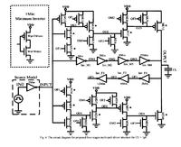
This past semester I've been taking a CMOS course in which we're using Cadence for designing low power mixed signal ASICs. This is nice and all, but I was thinking I could actually use a custom ASIC in my actual research (which deals with switchmode RF amplifiers). Basically one frustrating problem I face is how to effectively hard-switch FETs at high frequencies (like 120MHz). Ideally I want a nice clean 0-5V square wave for gate drive, but there aren't any off the shelf components meant to do this. The best approach I have is to use a bunch of high speed CMOS logic gates in parallel, but this doesn't seem to effective either. So I'm thinking I should try my own ASIC solution. Basically I want to make a ridiculously high power and high speed logic inverter. Fortunately my school gets to do a few free fab runs a year, so it wouldn't cost an arm and a leg to try...
My rough specs are as follows:
0.5um ONsemi process
Switching frequency: 125MHz
5V supply, r-r output swing
Drive 250pF load with tr/tf of <2ns (so at least 600mA of peak output current)
Overall delay is not a big deal, so long as the delay does not vary too much. But I don't want the duty cycle to be distorted significantly (+/-10%)
So what sort of issues would I run into? I have a feeling that I'll have to fan my inverter chain into many parallel chains which combine at the output (maybe each with their own pad, for lower bondwire ESL). Also with such large devices will I have to worry about shoot through current? Will I need some sort of modified inverter circuit to prevent this? Does this sound like total nonsense?

