Welcome to our site! EDAboard.com is an international Electronics Discussion Forum focused on EDA software, circuits, schematics, books, theory, papers, asic, pld, 8051, DSP, Network, RF, Analog Design, PCB, Service Manuals... and a whole lot more! To participate you need to register. Registration is free. Click here to register now.
i have this problem now.. i suppose to use IR Emitter and IR reciever sensors so that my motor will stop running once the door is fully open and fully closed. you have any idea how am i going to go about doing this?
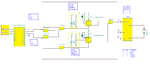
Let’s consider this circuit. I assume we are using optical sensors to control the Enable input of the driver circuit. The optical sensors output level change ‘ high’ for a temporary activation. Each sensor activation create a short pulse changing the status of the flip-flop circuits and disable the driver motor circuit.
Each time we send a new code for the motor section the logical circuits change also the status for the flip-flop circuits and thus enabling the motor driver circuit.
thanks man helped me to understand a lot.. a few questions though.. what is decoder ouput? i think u mean the receiver output? and here are my sensors im using, just wondering if its possible to fit the circuit.
EMITTER="The IR Emitter Circuit is a small piece of PCB consisting of power supply port, resistor and a IR emitter. Its purpose is to provide the IR Receiver a light source to change its output logic signal."
RECEIVER= "The output logic is tied to the controlling part when the logic reading change, the motor will stop running. Therefore the motor would stop the door when fully closed and stop the door when full opened."
That's the HT12D output. (decoder)
You may use any optical sensors, as long the sensor output level = 'high' for detecting the door closed/opened.
I was assuming opened door/ closed door cut the IR beams, forcing the sensors output to jump for a high level. So, in absence of the door the IR receivers get enough signal to keep the outputs to a low level.
By the way, there’s a mistake in your optical receiver drawing, reverse the IR photodiode (change also the symbol type in use).
can i use your circuit and replace with my sensors circuits instead? and u show me how i can do that? and whats wrong with my IR photodiode? its in the wrong direction ?
and the decoder output, i only can use 1 bit.. so thats why i need 2 (2 to 4 decoder), 1 to control the enable and the 2nd one to control 4 possible function..
This site uses cookies to help personalise content, tailor your experience and to keep you logged in if you register.
By continuing to use this site, you are consenting to our use of cookies.