Continue to Site

Welcome to EDAboard.com

Welcome to our site! EDAboard.com is an international Electronics Discussion Forum focused on EDA software, circuits, schematics, books, theory, papers, asic, pld, 8051, DSP, Network, RF, Analog Design, PCB, Service Manuals... and a whole lot more! To participate you need to register. Registration is free. Click here to register now.

[SOLVED] KVL, KCL, Nodal and Mesh Analysis

Status
Not open for further replies.
This fact caught my attention initially, but I assumed it had been done so delibearately, in order to measure the current flowing from the left half to the right half of the circuit. I vaguely remember a similar concept as this in the modified nodal analysis (MNA).

MNA does allow computing the current through a wire, but that's for later in the OP's studies.

Hatmpatn, once you post a new schematic with labels as I suggested, we can proceed with developing the nodal equations.
 
Okay, I have now a better understanding of what a node is and I hope the following schematic is the correct one.

uppg1nodanal.png
 

Sorry for taking so long to get back to you, but I had some other business I had to take care of.

Your schematic looks good. Now you need to do is set up your 5 nodal equations. The idea is to form an expression for each current leaving a given node, add them all up and set the sum equal to zero.

When a component such as a resistor is connected between a couple of nodes, such as for example, nodes V1 and V3, you simply divide the voltage across that node by the resistance of the resistor; that gives you the current through that resistor.

Here's how you set up the equation for the currents at node V1. The current direction is taken to be positive for currents leaving the node. What this means is that when you form the expression for the current in R2, while working at node V1, it is (V1-V3)/R2, not (V3-V1)/R2. Later, you will be working at node V3 and then the expression for the current leaving node V3 through R2 will be (V3-V1)/R2. This is the result of the convention that currents leaving a node are taken to be positive.

Sometimes, a resistor isn't connected between designated nodes, but it's connected between a node and ground, such as R8 and R9. In that case, the second voltage in the numerator expression is just zero. For example, the current leaving node V2 through resistor R8 is given by (V2-0)/R8, because the voltage at the left end of R8 is V2, and at the right end the voltage is zero (the voltage at the reference node, ground, is always taken to be zero; that's what it means to be the reference node).

Just remember that your expressions for the currents leaving the node will be a difference of voltages in the numerator of a fraction, such as (V1-V3), divided by a resistance in the denominator. The first voltage in the numerator expression will be the voltage at the node where you're forming a nodal equation.

For our first step, we'll ignore R10, E2 and E1. Nodes V1 and V2 will be a supernode because of the presence of E1, but for our first step, pretend E1 isn't even there.

So the equation at node V1 (call this Eq1) will be:

Eq1: (V1-V2)/R1 + (V1-V3)/R2 + .002 = 0

I've left R1 and R2 as symbolic quantities to make it clearer what's going on. It might be good to form all 4 equations that way to start, and later substitute numeric values when you form your matrix.

See if you can form the other 4 nodal equations.

By the way, R5 is just there to confuse you. A resistor in series with a current source essentially does nothing. It doesn't change the behavior of the current source, and in this circuit you can ignore it.
 
I'm perfectly satisfied with you just giving me the help, so you don't need to excuse yourself for taking a little longer than usual!
Although I must admit I wait anxiously for your responses ;-)
The equations for the nodes should be:

KCL@V1: (V1-V2)/1000Ω + (V1-V3)/1000Ω + .002 = 0

KCL@V2: (V2-V1)/1000Ω+V2/1000Ω+(V2-V4)/3000Ω=0

KCL@V3: (V3-V1)/1000Ω+(V3-V4)/4000Ω+(V3-V5)/2000Ω=0

KCL@V4: (V4-V2)/3000Ω+(V4-V3)/4000Ω+V4/7000Ω=0

KCL@V5: (V5-V3)/2000Ω+0.001+V5/9000Ω=0
 
Last edited:

I'm perfectly satisfied with you just giving me the help, so you don't need to excuse yourself for taking a little longer than usual!
Although I must admit I wait anxiously for your responses ;-)
The equations for the nodes should be:

KCL@V1: (V1-V2)/1000Ω + (V1-V3)/1000Ω + .002 = 0

KCL@V2: (V2-V1)/1000Ω+V2/1000Ω+(V2-V4)/3000Ω=0

KCL@V3: (V3-V1)/1000Ω+(V3-V4)/4000Ω+(V3-V5)/2000Ω=0

KCL@V4: (V4-V2)/3000Ω+(V4-V3)/4000Ω+V4/7000Ω=0

KCL@V5: (V5-V3)/2000Ω+0.001+V5/9000Ω=0

Very good! One little problem with the 5th equation. Notice that the current source I02 is floating; neither end of it is connected to ground unlike I01 which does have one end grounded.

Thus, I02 withdraws a .002 A current from V1 (a positive current), but also injects a .002 A current into V5 (a negative current), so KCL@V5 should be:

KCL@V5: (V5-V3)/2000Ω+0.001+V5/9000Ω-.002=0[/QUOTE]

Now, V1 and V2 together form a supernode. The way to deal with that is similar to the method we used with the mesh equations. Equations KCL@V1: and KCL@V2: must be modified. Let's allow the first to be the supernode equation and the second will become a constraint equation. The supernode equation can be formed by simply adding the first two equations:

(V1-V2)/1000Ω + (V1-V3)/1000Ω + .002 = 0
(V2-V1)/1000Ω+V2/1000Ω+(V2-V4)/3000Ω=0
--------------------------------------------------------
(V1-V2)/1000Ω+ (V1-V3)/1000Ω+.002+V2/1000Ω+(V2-V1)/1000Ω+(V2-V4)/3000Ω=0

Which becomes:

V1/1000Ω+V2/1000Ω+V2/3000Ω-V3/1000Ω-V4/3000Ω = -.002

The constraint equation is V1 -V2 = 3; this is now the second equation.

Form your matrix system (post it so I can see if there are any errors) and solve it, showing the results.

When you get this, we can move on to deriving the Thevenin equivalent.
 
Last edited:
Alright, here is my result.

KCL@V1: V1(1/1000Ω)+V2(1/1000Ω+1/3000Ω)-V3(1/1000Ω)-V4(1/3000Ω) =-0.002

KCL@V2: V1-V2=3

KCL@V3: -V1(1/1000Ω)+V3(1/1000Ω+1/4000Ω+1/2000Ω)-V4(1/4000Ω)-V5(1/2000Ω)=0

KCL@V4: -V2(1/3000Ω)-V3(1/4000Ω)+V4(1/3000Ω+1/4000Ω+1/7000Ω)= 0

KCL@V5: -V3(1/2000Ω)+V5(1/2000Ω+1/9000Ω)=0.001

Input in matlab: A=[1/1000 (1/1000+1/3000) -1/1000 -1/3000 0; 1 -1 0 0 0; -1/1000 0 (1/1000+1/4000+1/2000) -1/4000 -1/2000; 0 -1/3000 -1/4000 (1/3000+1/4000+1/7000) 0; 0 0 -1/2000 0 (1/2000+1/9000)]

B=[-0.002; 3; 0; 0; 0.001]

A1*B= [1.6487; -1.3513; 1.8423; 0.0140; 3.1437]
Which means: V1=1.6487V V2= -1.3513V V3=1.8423V V4=0.0140V V5=3.1437V

I overlooked a sign error in your equation 5 in post #24. Note that both currents I01 and I02 inject a current into V5. That is a current with a negative sign because the current is entering the node. Also, you forgot to include the current injected into V5 from IO2, so the correct equation 5 should be:

KCL@V5: (V5-V3)/2000Ω-0.001+V5/9000Ω-.002=0
or
KCL@V5: (V5-V3)/2000Ω+V5/9000Ω = .001+.002

This changes your B vector to:

B=[-0.002; 3; 0; 0; 0.003]

What do you get with this change? I'm sure you will get the right result. This will give you the open circuit voltage at V5. This is the value of Vth, the Thevenin equivalent voltage of the circuit without R10 and E2. Your original problem wanted the Thevenin equivalent at the right end of R10 and E2, which we have ignored so far, but clearly Vth at the right end of E2 is just the voltage V5 minus 6 volts.

Next, to determine Rth, the Thevenin resistance of the circuit without R10 and E2, solve the system with this B vector:

B=[0; 0; 0; 0; 1]

Show your result.

The last element in your result vector will be the voltage at node V5 when a test current of 1 amp is applied to node V5. That is the value of Rth (at node V5) of the circuit without R10 and E2. The presence of R10 will increase the resistance seen at the right end of your original circuit by the amount of R10; this will be Rth for your original circuit.

If you're up for some more calculations, I'll go back to the mesh solution and show how to get Vth and Rth from it.
 
With B=[-0.002; 3; 0; 0; 0.003]
A-1*B= [2.8703; -0.1297; 4.2315; 1.3972; 8.3713]
Which means: V1=2.8703V V2= -0.1297V V3=4.2315V V4=1.3972V V5=8.3713V

So the voltage at the right end of E2 should be 8.3713V-6V=2.3713V

So, lets see if I understand correctly.

And with the vector B=[0; 0; 0; 0; 1]
I get the result with the same inverted A matrix: A1*B [610.8 610.8 1194.6 619.6 2613.8]

The last element is 2613.8Ω, the value at node V5.

This value + R10 gets us the resulting Rth in the thevenin equivalent circuit.

2613.8Ω+10000Ω=12613.8Ω

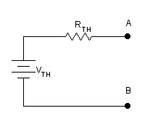
According to me, we now have Rth and Vth in this schematic:

circuitThevenin.gif

Am I correct? Probably not, since I dont see the usage of the mesh analysis yet.
 

With B=[-0.002; 3; 0; 0; 0.003]
A-1*B= [2.8703; -0.1297; 4.2315; 1.3972; 8.3713]
Which means: V1=2.8703V V2= -0.1297V V3=4.2315V V4=1.3972V V5=8.3713V

So the voltage at the right end of E2 should be 8.3713V-6V=2.3713V

So, lets see if I understand correctly.

And with the vector B=[0; 0; 0; 0; 1]
I get the result with the same inverted A matrix: A1*B [610.8 610.8 1194.6 619.6 2613.8]

The last element is 2613.8Ω, the value at node V5.

This value + R10 gets us the resulting Rth in the thevenin equivalent circuit.

2613.8Ω+10000Ω=12613.8Ω

According to me, we now have Rth and Vth in this schematic:

Remember that Rth can be calculated from the open circuit voltage divided by the short circuit current. Or if we know Vth and Rth, the short circuit current is given by Vth/Rth. The values we have derived here give 2.3713/12613.8 = 1.8799 mA.

In post #15 you got 1.1 mA for I6, which should be the short circuit current for your original circuit including R10 and E2. This is not the same as 1.8799 mA.

Now we see the virtue of solving the circuit by two different methods and comparing results.

I made a sign error in post #11 when I gave the equation for mesh I6 as:

-6V+9kΩ(I6-I5)+10kΩ(I6)=0

It should be +6V+9kΩ(I6-I5)+10kΩ(I6)=0 instead.

Change the sixth element of the B vector in post #15 from +6 to -6 and solve again. You should get a value for I6 of 0.18799 mA which matches the value we got from Vth/Rth calculation above.

So after fixing this error we get a value for the short circuit current from the mesh equations of 0.18799 mA.

Now we need the open circuit voltage. We could get this by eliminating mesh 6 from the equations and solving. Then the fifth element of the solution vector would be the current through R9 with R10 and E2 missing. Multiplying this current by 9000 would give us the voltage across R9; this would be the same voltage as V5 we got from the nodal solution from which we can subtract 6 and get Vth. Dividing Vth by 0.00018799 would give us Rth.

Another way to do it is to apply a 1 volt test voltage in series with R10 and E2 and re-solving the mesh equations in post #15. We fixed the error in those equations by changing the +6 in the B vector to -6; this gave us an I6 current of 0.00018799 A.

Adding a 1 volt test voltage in series with R10 and E2 is done by simply changing the -6 to -5. Solving again gives an I6 current of 0.000267268 A.

The resistance seen by that test voltage is calculated by dividing the 1 volt test voltage by the change in the current that occurred as a result of applying the test voltage.

The calculation is Rth = 1V/(.000267268A-.00018799A) = 12613.8Ω

The Thevenin equivalent has now been found from both the mesh equations and nodal equations.
 
This is so awesome! So my solution is now right in front of me? Rth=12613.8Ω and Vth=2.3713V
Thank you a hundred times The Electrician. This must have taken alot of time from your hands and it warms my heart that a person who don't really know me would help me like this!

I bet this thread will help alot of other students aswell, so that makes me proud!
 

I'm always glad to help somebody who learns as eagerly as you have.

Good luck with your continuing studies. :-D
 
Here's a little follow-up!

According to my teacher the short-circuit current and the open-circuit voltage are incorrect.
I've tried to go through the equations again but without finding the source of error.

Rth is correct tho, he says.
 

He won't show me the correct values, he thinks I should figure it out myself but looking at the equations and currents going in and out of the nodes it really looks right to me.
 

I ran a simulation with Spice and got the same results as the mathematical analyses.

Here's a possible explanation for the discrepancy. I notice that the values of the resistors are mostly the same as the numeric part of their designators:

R1 = 1k
R3 = 3k
R4 = 4k
R5 = 5k
R7 = 7k
R9 = 9k
R10 = 10k

The exceptions are R2, R6 and R8. Why doesn't R2 = 2k, R6 = 6k and R8 = 8k?

Double check that your resistor values match the problem your teacher gave you, and that it's wired up exactly the same.

Keep in mind that teachers sometimes make mistakes, but you have to be very careful to suggest such a thing. You will want to triple check your own work!
 
I see what you mean by that but the resistors and their values are correct.

I have e-mailed my teacher and he hinted that there is something wrong with my mesh analysis and that it is common in these types of problems with symbol error.

He's not the kind that you want to accuse of making an error, so I'll quadruple-check this bad boy! ;)

------------------------------

Wait a minute! I've done an error putting the voltage source E2 at the wrong direction. So this is the correct schematics!

uppg1.png

So it should be 8.3713V+6V=14.3713V right?

- - - Updated - - -

I really can't think today. I need to change the sign in some of the equations again. I think I'll manage on my own.
In this case, the post #15 is probably correct. I'll get back with the correct answers(hopefully).
 
Last edited:

Yes. This will make Vth = 14.3713, and the short circuit current will be .00113933A.

Rth will remain the same.

You should only need to change the sign in one equation in the mesh analysis for the short circuit current, and no changes are needed in the nodal analysis.

It's easy to make sign errors in analyses like this. This is why people use simulators for circuits that are even more complicated. The probability of getting a correct result by hand approaches zero as the circuit has more than about 10 nodes. :sad:
 
Hey! I got the problem approved by the teacher!

Marking this thread as [SOLVED] and hope that future electronics students can find this thread useful!
Thanks again to The Electrician!
 

Status
Not open for further replies.

Part and Inventory Search

Welcome to EDABoard.com

Sponsor

Back
Top