Continue to Site

Welcome to EDAboard.com

Welcome to our site! EDAboard.com is an international Electronics Discussion Forum focused on EDA software, circuits, schematics, books, theory, papers, asic, pld, 8051, DSP, Network, RF, Analog Design, PCB, Service Manuals... and a whole lot more! To participate you need to register. Registration is free. Click here to register now.

Kirchoffs and maximum power transfer

Status
Not open for further replies.

matthew187

Junior Member level 2
Joined
Apr 10, 2013
Messages
20
Helped
0
Reputation
0
Reaction score
0
Trophy points
1,281
Visit site
Activity points
1,433
Hi Folks
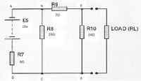
I need a bit of help, My weakness is kirchoffs law and algebra, I know but I still give it a try. For this task I am required to calculate the value of the load (RL) using kirchoffs and then I have to find the maximum power transfer for the circuit. I have attempted to calculate the load (RL) using kirchoff now the bit that I am confused on is am I looking for the resistance of the Load (RL) or the current in the load (RL). Which figure is required to calculate the maximum power transfer? is it the current or resistance of the load (RL)? If it is the current is my calculations correct? and if its the resistance I need to calculate, how do I figure that out because I have no clue where to start:(
 

Attachments

  • Max power transfer.pdf
    316.8 KB · Views: 142

For max power transfer, RL must equal the source impedance. In this case, Rsource = R10 || (R9 + (R8 || R7))

where || means "in parallel with".


So all what I have done is wrong? Can I achieve this using kirchoffs?

By Kirchhoff? --> Of course!

1st Yyou must calculate the voltage output (Vo=V_EF) without load (Rl=∞)
2nd Calculate the short circuit current: Isc (Rl=0)
3rd Finally Rl = Vo / Icc , corresponding to the Thevenin resistance and thus has maximum power.

His calculation was fine until the last paragraph, that is a complete nonsense.
 

So lets forget that last paragraph which is "sub into equation". so for I2 i got 0.293a so where do I go from here now how do I calculate the voltage output? Or the short circuit current? Or the RL
 

the way I would do it, would be to take the loop ABCD and see how it reacts.
So Vo = 25/34 X 15 = 10.71volts and its internal resistance is 9 in parallel with 25 = 225/34 = 6.167 ohms
now add on loop EF
so we have A 10.712 battery with 6.167 + 7 in series and a 24 ohm load, so new Vo = 24/27.167 volts = 9.463 V with 13.167 in parallel with 24 = 13.167 X 24/37.167 = 8.5 ohms in series.
So for Pmax Rl = 8.5 ohms. The voltage across it is .5 X Vo = 9.463/2 = 4.732, so Po = 4.732 X 4.732 /8.5 = 2.634 Watts
Frank
 

So lets forget that last paragraph which is "sub into equation". so for I2 i got 0.293a so where do I go from here now how do I calculate the voltage output? Or the short circuit current? Or the RL

Without load you got I2=.293A ==> Vo = 24*I2 = 7.032V

Now the 2nd part: Isc

(9+25)*I1 - 25*I2 = 15
-25*I1 + (25+7)*I2 = 0 <-- short circuit at R10

solving system... Isc = I2 = 0.81A

Finally: Rmaxpow = Rthev = Vo/Isc = 8.68ohm


That match the suggestion of godfreyl (the shortest path): R10 || (R9 + (R8 || R7)) = 1/(1/24+1/(7+1/(1/9+1/25))) = 8.688037529
 

Without load you got I2=.293A ==> Vo = 24*I2 = 7.032V

Now the 2nd part: Isc

(9+25)*I1 - 25*I2 = 15
-25*I1 + (25+7)*I2 = 0 <-- short circuit at R10

solving system... Isc = I2 = 0.81A

Finally: Rmaxpow = Rthev = Vo/Isc = 8.68ohm

How did you caculate isc=i2= 0.81a?

How did you get these two unknowns? (9+25)*I1 - 25*I2 = 15
-25*I1 + (25+7)*I2 = 0
 

It is exactly the same procedure and the same notation as used you.

Solve for I2 two times: First for open circuit (Rl = inf), after for shorted (Rl = 0)

In both cases it is a 2x2 equations system that can be solved by your preferred method (Cramer, Gauss, substitution).
 

How did you...
I worked it out like this:

  1. Firstly, start with just the battery and R7. That gives you a voltage source of 15V with a source impedance of 9Ω
  2. Now add R8 to the circuit. R7 and R8 form a voltage divider, so now voltage = 15V*R8/(R7+R8) = 11.03V and source impedance = R7||R8 = 6.62Ω
  3. Now add R9 to the circuit. Voltage is still 11.03V, but now source impedance = 6.62Ω+R9 = 13.62Ω
  4. Finally, add R10. This makes a voltage divider again. The voltage across R10 = 11.03V*R10/(R10+13.62Ω) = 7.04V and the impedance = R10||13.62Ω = 8.69Ω
So the open circuit voltage is 7.04V and the source impedance is 8.69Ω.
Short circuit current = 7.04V/8.69Ω = 810mA.
Optimum load resistance for max power = source impedance = 8.69Ω.


Now when we connect the 8.69Ω load to the circuit, we can calculate everything else like this:

  1. Voltage across load = 7.04V*Rload/(Rload+Rsource) = 3.52V
  2. Current through load resistor = 3.52V/8.69Ω = 405mA
  3. Current through R10 = 3.52V/24Ω = 147mA
  4. Current through R9 = current through R10 + current through load resistor = 405mA + 147mA = 552mA
  5. Voltage across R9 = 552mA*7Ω = 3.86V
  6. Voltage across R8 = voltage across R9 + voltage across R10 = 3.52V + 3.86V = 7.38V
  7. Current through R8 = 7.38V/25Ω = 295mA
  8. Voltage across R7 = 15V - voltage across R8 = 15V - 7.38V = 7.62V
  9. Current through R7 = 7.62V/9Ω = 847mA
 

Without load you got I2=.293A ==> Vo = 24*I2 = 7.032V

Now the 2nd part: Isc

(9+25)*I1 - 25*I2 = 15
-25*I1 + (25+7)*I2 = 0 <-- short circuit at R10

solving system... Isc = I2 = 0.81A

Finally: Rmaxpow = Rthev = Vo/Isc = 8.68ohm

How did you caculate isc=i2= 0.81a?

How did you get these two unknowns?

Thats the bit I misunderstood how to calculate I2 without the load,

(9+25)*I1 - 25*I2 = 15 what are the values for I1 and I2 in this equation?
-25*I1 + (25+7)*I2 = 0 and what is the value for I1 and I2 in this equation?

Then which numbers did you calculate to get isc=I2=0.81a

This is the bit I don't understand as this is the important bit as long as I understand this I am confident I can complete the original question.
 

@Eduardo and Mathew:
Maybe there's some confusion between you about which currents are I1, I2, I5 etc. They're not marked on the diagram, so we don't know for sure which current flows through which resistor.
 

@Eduardo and Mathew:
Maybe there's some confusion between you about which currents are I1, I2, I5 etc. They're not marked on the diagram, so we don't know for sure which current flows through which resistor.

Oh I was meant to attach this aswell, theres only I1 and I2 I knew that I2= 0.293a

(9+25)*I1 - 25*I2 = 15
-25*I1 + (25+7)*I2 = 0 <-- short circuit at R10

solving system... Isc = I2 = 0.81A

I want to know how my friend eduardo got the above answer because that is the format I am trying to use.
 

Attachments

  • maxpower I1 I2.png
    maxpower I1 I2.png
    61.3 KB · Views: 112

In the PDF you wrote:

Loop ABCD
15 = 9I1 + 25(I1-I2) = 34I1 - 25I2 (eq1)

Loop BEFC
0 = 7I2 + 25(I2-I1) + 24I2= -25I1 + 56I2 (eq2)

Right?


Then you solve the system for the variable I2 doing:
25 x eq1 + 34 x eq2 --> 375 = 1279I2 --> I2 = .293

Right?


But... What is represented by I2? --> Is the current at R10 when Rl is disconected.

Right?

---------------------------------

Now the 2nd step: Short circuit.

Loop ABCD
15 = 9I1 + 25(I1-I2) = 34I1 - 25I2 (eq1)

Loop BEFC
0 = 7I2 + 25(I2-I1) = -25I1 + 32I2 (eq2) <-- because R10 is shorted

Right?

Then you solve the system for the variable I2 doing:
25 x eq1 + 34 x eq2 --> 375 = 463I2 --> I2 = .81

Right?

Fantastic you guys are genius.
 

Hi again before I hand this paper in I just wanted to see if I was on the right lines I've understood what everything means, but I am struggling to present my work in the manner it was requested. I have drew some diagrams and wrote the equations but I just want to know if the format of the diagrams and equations are correct? I understand that after working out I2 with kirchoffs we then focused on finding the resistance for RL using thevenins equivalent but I just wanted to know if my diagrams and the way I wrote my equations are correct?
 

Attachments

  • Max power.pdf
    431 KB · Views: 118
Last edited:

Hi

First page, second line under "Loop ABCD":
"15v = 10ΩI₁+ 25ΩI₁ - 25ΩI₂" should be "15v = 9ΩI₁+ 25ΩI₁ - 25ΩI₂"

Second page, first line:
"Vo = 0.293a * 24ΩI² = 7.032v" should be "Vo = 0.293a * 24Ω = 7.032v"

The calculation of ISC is complete nonsense, even if it gives the correct answer.
 

Hi

First page, second line under "Loop ABCD":
"15v = 10ΩI₁+ 25ΩI₁ - 25ΩI₂" should be "15v = 9ΩI₁+ 25ΩI₁ - 25ΩI₂"

Second page, first line:
"Vo = 0.293a * 24ΩI² = 7.032v" should be "Vo = 0.293a * 24Ω = 7.032v"

The calculation of ISC is complete nonsense, even if it gives the correct answer.

So I'm assuming the diagram for vo is correct? How do I go about writing the formula for isc and what diagram is used? Those errors that you have pointed out where typos but I appreciate that you spotted them. This is the last bit of the assignment and then I can hand it in I'm pretty desperate to understand.
 

Status
Not open for further replies.

Part and Inventory Search

Welcome to EDABoard.com

Sponsor

Back
Top