Continue to Site

Welcome to EDAboard.com

Welcome to our site! EDAboard.com is an international Electronics Discussion Forum focused on EDA software, circuits, schematics, books, theory, papers, asic, pld, 8051, DSP, Network, RF, Analog Design, PCB, Service Manuals... and a whole lot more! To participate you need to register. Registration is free. Click here to register now.

Keypad interface in pic16f877

Status
Not open for further replies.

ecaits

Member level 4
Joined
Jan 16, 2014
Messages
76
Helped
0
Reputation
0
Reaction score
0
Trophy points
6
Activity points
579
Dear All,

To interface keypad in pic16f877, will I need to connect +Vcc with resistor to input port to detect the switched pressed???

Can you give me logic of key detection???

Thank you
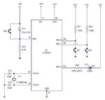
 

key-interface.jpg
A high read at pin P0.0 indicates switch S1 is open and a low indicates switch is closed.
 

It depends entirely on how you have connected the keypad. Techgreeds example shows how to do it with individual switches (note the '877 reset works the other way around) but not if you have a keypad in a matrix.

The general rule is the input pins must be held in their 'inactive' state until a key is pressed and this *may* require the use of an external pull-up or pull-down resistor depending on how you wire it up and drive it. What you must never do is leave an input floating until a key connects it to something, that would result in random signals. Some of the pins on the '877 have internal pull-up resistors which you may be able to use to save components.

Brian.
 

First of all, when you say keypad are you thinking of a matrix? If so, how many keys in the pad? How many keys in total?
How many pins are available on your PIC for this keypad interface?
 

Status
Not open for further replies.

Part and Inventory Search

Welcome to EDABoard.com

Sponsor

Back
Top