Continue to Site

Welcome to EDAboard.com

Welcome to our site! EDAboard.com is an international Electronics Discussion Forum focused on EDA software, circuits, schematics, books, theory, papers, asic, pld, 8051, DSP, Network, RF, Analog Design, PCB, Service Manuals... and a whole lot more! To participate you need to register. Registration is free. Click here to register now.

JDM With External Power - Some Help Needed

Status
Not open for further replies.

sole_developer

Junior Member level 3
Joined
Oct 17, 2010
Messages
31
Helped
0
Reputation
0
Reaction score
0
Trophy points
1,286
Activity points
1,524
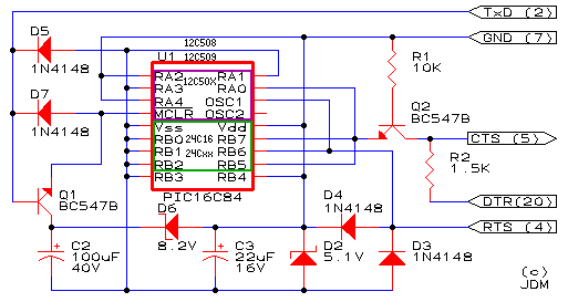
I have designed the following, however for some reason it is not working! I'am probably going to scrap this, but I though I would check with u guys one last time!...........

View attachment FINAL BOARD.pdf

Everythiing seems to be workign when I test the pins...but when I try to program something, nothing works.........Iam probably going to scrap it and try to build a USB Programmer........but I just don't get why its not working........Everything seems to be fine on pencil and paper!!!

thanks again
 

are you using a USB to serial converter for this? if you are then it will not work because JDM makes use of negative voltage from the serial port. JDM works great on a native serial port.
 

Well...actually i looked at couple of designs and made this myself......I am supplying external voltage to the board...the problem is everything seems OK when I even test the voltages....but it doesn't program anything...........
I am getting 5v on VCC and VSS is grounded.......and the PGC & PGD when they are high give me 8 volts........I am using a COM PORT, not USB

But still, i don't know why it is not programming anything........i tried programming a 24C02 chip, it didn't work.......Anyways, I think i will try to make a PIKIT2 clone or something......

I mean, even when I don't put a chip and click on read.....the programming software is reading all 00's from somewhere!!!.........and programming also, i see that data flowing (have put LEDs) but still nothing...!!
 
Last edited:

well your design lacks voltage limiting diodes, try and assemble the real JDM, it works well. Even if you buil a clone PIC Kit 2 you need a way to program the PIC kit firmware. beware 8volts on PGC and PGD can damage the PIC.

 
Thank you...I completely forgot about those!!! NO wonder...anyways......will check what happens after I add them....and in the meantime......I have though about making a power supply (Variable), switch for either 12V or 13V (some chips need 12V!)........The LM317.bmp LM317 structure, the one I have designed is in the pdf....Could you please help me with your experiance whether or not what I have designed will work...

THanks in advance!

(PS: I used the voltage calculator on LM317 Voltage Calculator - Electric Circuit)

PS: the '+13/+12' pin iwll be hte output based on posiution of the switch PWR
 

Attachments

  • POWER BOARD.pdf
    14.4 KB · Views: 129
  • LM317.bmp
    236.3 KB · Views: 121
Last edited:

Status
Not open for further replies.

Similar threads

Part and Inventory Search

Welcome to EDABoard.com

Sponsor

Back
Top