AlienCircuits
Member level 5

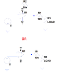
I have a real circuit that someone designed, and I am curious about why there is a resistor of 10k included in the feedback path. The circuit basically takes a voltage and buffers it to be measured by a DMM or oscilloscope, and so the load represents the input impedance of a probe.

When I use my circuit analysis, I see that no current should flow in this feedback resistor with an ideal opamp, and so there is no voltage drop across it. I think a feedback with 0 resistance would work just as well. I also think that this resistor could degrade the frequency response, but this is a DC application and not that important to consider either way (unless that is there to reduce bandwidth on purpose?).
I think that the other 10k resistor in series with the load is there to protect the opamp against short circuit conditions.
So, why would I want this resistor in the feedback path anyway?


