Continue to Site

Welcome to EDAboard.com

Welcome to our site! EDAboard.com is an international Electronics Discussion Forum focused on EDA software, circuits, schematics, books, theory, papers, asic, pld, 8051, DSP, Network, RF, Analog Design, PCB, Service Manuals... and a whole lot more! To participate you need to register. Registration is free. Click here to register now.

Is there any way to sovle the crossregulation of multi-output flyback now ?

Status
Not open for further replies.

L_jack_xing

Junior Member level 2
Joined
Nov 16, 2013
Messages
24
Helped
0
Reputation
0
Reaction score
0
Trophy points
1
Activity points
186
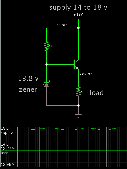
My target is 3 output flyback convertor,the main output is 5V/3A,the auxiliary output is ±13V/0.25A.There is a problem when the 5V output load 3A and ±13V unload,the voltage of ±13V will get to ±18V.Is there any solution can make ±13V not over ±14.5V in this situation?Another, the No-load power consumption must be under 0.5W .And postregulation,mag amp is not allow to use.Thanks for your help.:-D
 

Multiple voltage sensing is the general method as below. Fed.jpg
 

Thank you.Can load regulation of main output satisfy 1% in this method?I had saw a pratical case that the load regulation can only reach 3% in this method.
 

1% cross regulation really isn't feasible for flyback topology, unless you somehow get a transformer with extremely low ESR and leakage inductance. At that point it's likely more cost effective to use post regulation or another topology.
 

Transformer secondary winding resistance, Leakage inductance and diode voltage drops will affect the cross regulation. Below points are extreme condition for achieving 1% cross regulation.
1. Make secondary DC and AC resistance (Skin effect) extremely low as possible.
2. Make low leakage inductance.
3. Use low drop diode or use synchronous rectifier (MOSFET).
4. Use low ESR capacitor or connect more parallel capacitor.
5. Increase number of turns by 10 % or more without affecting the turn ratio.
6. Use continuous conduction flyback mode. It will improve the cross regulation.
7. Introduce a low value non polar capacitor in between positive (dot) terminals of secondary windings. It will improve the cross regulation at low current load.
 
1% cross regulation really isn't feasible for flyback topology, unless you somehow get a transformer with extremely low ESR and leakage inductance. At that point it's likely more cost effective to use post regulation or another topology.

I mean the main output load regulation must be 1% at any load condition.And the unregulated output in 10% load regulation is ok. I did a series of experiment ,stacked windings,multiple feedback,but they doean't work well.The load regulation of 13V output still over 3% and the 5V's regulation become worse.

- - - Updated - - -

Transformer secondary winding resistance, Leakage inductance and diode voltage drops will affect the cross regulation. Below points are extreme condition for achieving 1% cross regulation.
1. Make secondary DC and AC resistance (Skin effect) extremely low as possible.
2. Make low leakage inductance.
3. Use low drop diode or use synchronous rectifier (MOSFET).
4. Use low ESR capacitor or connect more parallel capacitor.
5. Increase number of turns by 10 % or more without affecting the turn ratio.
6. Use continuous conduction flyback mode. It will improve the cross regulation.
7. Introduce a low value non polar capacitor in between positive (dot) terminals of secondary windings. It will improve the cross regulation at low current load.


Thank you.I will try.Ponits 3,4 would increase cost so i can't use.
 

Ponits 3,4 would increase cost so i can't use.
I fear, the effort for making extra low leakage transformers might be even more expensive.

In my view, LDO post regulators for the +/-13 V nodes could turn out as the best trade-off.
 

I fear, the effort for making extra low leakage transformers might be even more expensive.

In my view, LDO post regulators for the +/-13 V nodes could turn out as the best trade-off.


Two LDO cost 0.6USD at least,furthermore ,it will reduse efficiency.I try again today ,only can make the +/-13V under 15V when it unload and the 5V is full load.I will make some experiments tomorrow.Thanks for your suggestion.:)
 

Well, there is always a ground current from the housekeeping
(reference, error amp, etc.) circuitry. Trivial, perhaps, but
not "none". Some older bipolar "LDOs" of my acquaintance
were actually pretty hungry, and these were higher voltage
types like are being talked about. The CMOS LDOs/ULDOs
of more modern vintage are better, generally, but you have
to look at the numbers.
 

There are no LDO losses with unloaded outputs.

Yeah,But LDO will drag down the efficiency of entire flyback convertor when the +/-13V loaded.

- - - Updated - - -

Well, there is always a ground current from the housekeeping
(reference, error amp, etc.) circuitry. Trivial, perhaps, but
not "none". Some older bipolar "LDOs" of my acquaintance
were actually pretty hungry, and these were higher voltage
types like are being talked about. The CMOS LDOs/ULDOs
of more modern vintage are better, generally, but you have
to look at the numbers.

The CMOS LDOs may more expensive,I see.I will try it if some project isn't request for a low cost.Thank you.
 

I mean the main output load regulation must be 1% at any load condition.And the unregulated output in 10% load regulation is ok. I did a series of experiment ,stacked windings,multiple feedback,but they doean't work well.The load regulation of 13V output still over 3% and the 5V's regulation become worse.
If your main output has such poor load regulation then something is wrong with your controller, you should investigate that first. It shouldn't be difficult to get load regulation much below 1% using simple PI control (assuming you're actually measuring the output voltage at the feedback point).
 

There is this type of low dropout regulator. It's simple and easy (after it's adjusted), however it lacks the features of an IC regulator.

Some power is wasted of course. The higher the transistor gain, the less current needs to go through the bias network.


The term LDO regulator is sometimes used quite "boundless". I think, a regulator that actually deserves the name can be expected to have considerably below 500 mV dropout at rated current, e.g. 100 or 200 mV. It's really misleading when regulators like LM1117 with > 1V dropout voltage are advertised as "LDO". From this viewpoint, the circuit in post #13 can't be designated a LDO, it has > 0.6 V droput at low load, continuously rising with increasing current.

A bipolar LDO must use a PNP series transistor, by nature of the circuit it causes a ground terminal current of Iload/B. That's slightly reducing LDO efficiency, but I still think it can be an option for auxilary outputs of a SMPS.

CMOS regulators can use a PMOS pass transistor and achieve nearly ideal LDO efficiency. Unfortunately they have usually restricted voltage range, e.g. 12V.
 

There is this type of low dropout regulator. It's simple and easy (after it's adjusted), however it lacks the features of an IC regulator.

Some power is wasted of course. The higher the transistor gain, the less current needs to go through the bias network.


Oh,i use this circuit before and maybe it will work.The more 50 cent cost will be accepted.But I fear the temperature of NPN triode will rise too high when the +/-13V is full load.

- - - Updated - - -

The term LDO regulator is sometimes used quite "boundless". I think, a regulator that actually deserves the name can be expected to have considerably below 500 mV dropout at rated current, e.g. 100 or 200 mV. It's really misleading when regulators like LM1117 with > 1V dropout voltage are advertised as "LDO". From this viewpoint, the circuit in post #13 can't be designated a LDO, it has > 0.6 V droput at low load, continuously rising with increasing current.

A bipolar LDO must use a PNP series transistor, by nature of the circuit it causes a ground terminal current of Iload/B. That's slightly reducing LDO efficiency, but I still think it can be an option for auxilary outputs of a SMPS.


CMOS regulators can use a PMOS pass transistor and achieve nearly ideal LDO efficiency. Unfortunately they have usually restricted voltage range, e.g. 12V.


I agree.The temperature of triode will rise too hight and the efficentcy will go down.But the restricted voltage is a problem.
 

Status
Not open for further replies.

Similar threads

Part and Inventory Search

Welcome to EDABoard.com

Sponsor

Back
Top