Continue to Site

Welcome to EDAboard.com

Welcome to our site! EDAboard.com is an international Electronics Discussion Forum focused on EDA software, circuits, schematics, books, theory, papers, asic, pld, 8051, DSP, Network, RF, Analog Design, PCB, Service Manuals... and a whole lot more! To participate you need to register. Registration is free. Click here to register now.

Is there a Brewster angle formulation for a curvilinear or hemispherical surface?

Status
Not open for further replies.

kae_jolie

Full Member level 4
Full Member level 4
Joined
Oct 13, 2006
Messages
234
Helped
9
Reputation
18
Reaction score
8
Trophy points
1,298
Activity points
3,158
Is there a Brewster angle formulation for a curvilinear or a hemispherical surface? The equations I find in the books are for Brewster angles on flat surfaces? Would the same equations apply to the curvilinear or hemispherical surfaces?

Thanks.
 

The Brewster angle has to be applied to the plane (or the line, in case of 2D) tangent to the surface you are considering, at the incident point. If you beam is not punctiform, then you have to calculate the scattered rays point-by-point within the aperture.
 

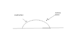
albbg, thank you for the answer. I have a half-circle round surface which I would like to couple most EM power to. I found say 70 degrees to be the Brewster angle given the dielectric properties of this surface. Since the surface is round, there will be multiple planes tangent to the round surface. Where would the antenna be placed? At 70 degrees on each of those multiple tangent lines?
 

Your geometry is not clear to me. Could you post a drawing to better explain ?
 

diagram.PNG

Here you go.
 

Referring to the following picture:

PerEDA.jpg

inside the aperture of the antenna, I think you should calculate the angle formed from the rays (coming from the antenna) to the tangent of surface at intersection point (f.i. α, β and γ in the picture) and calculate the reflection coefficient. The optimum positioning should minimize the sum of the reflection coefficients calculated from each ray. In the example I took 3 rays, but to improve precision you should consider more rays.
 
Last edited:

Referring to the following picture:

View attachment 86516

inside the aperture of the antenna, I think you should calculate the angle formed from the rays (coming from the antenna) to the tangent of surface at intersection point (f.i. α, β and γ in the picture) and calculate the reflection coefficient. The optimum positioning should minimize the sum of the reflection coefficients calculated from each ray. In the example I took 3 rays, but to improve precision you should consider more rays.

I agree somewhat. However, while ray tracing (where brewster angle makes sense) may work well at optical frequencies where the wavelength is tiny....at microwave frequencies I would treat the ray tracing as just an approximation. You really need to use a 3D electromagnetic simulator program to accurately analyze the radiation.
 

Status
Not open for further replies.

Part and Inventory Search

Welcome to EDABoard.com

Sponsor

Back
Top