Continue to Site

Welcome to EDAboard.com

Welcome to our site! EDAboard.com is an international Electronics Discussion Forum focused on EDA software, circuits, schematics, books, theory, papers, asic, pld, 8051, DSP, Network, RF, Analog Design, PCB, Service Manuals... and a whole lot more! To participate you need to register. Registration is free. Click here to register now.

Is my design correct? Proteus simulates it but I need to change some values.

Status
Not open for further replies.

Circuitmonster1032

Newbie level 3
Joined
Nov 21, 2016
Messages
3
Helped
1
Reputation
2
Reaction score
1
Trophy points
3
Activity points
25
Hello everybody,

I'm designing a firing circuit for an SCR TIC106D, the datasheet shows a maximum Igt current of 200uA. But if I simulate it in proteus it doesn´t work as expected. Here are some screenshots of my design.

I still don´t have the real parts, so I can´t test it. Therefore I was wondering If this would work.
Design1.PNG

With this values the simulation runs and I get the expected waveform:
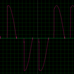
Design2.PNG

According to my calculations if the max gate current is 200uA I need a resistor of around 800K. If I enter this value in proteus the optocoupler is not activated.
Am I doing something wrong?

will appreciate your help,

Regards
 

Hi,

You marked the thread as solved...

According gate current:
It's a bit confusing. The gate may withstand 200mA, but to trigger it needs max 0.2mA, so you should drive the gate with a current somewhere inbetween.

And it seems both scr are in series. Is this what you want? Maybe this causes some problems.

Klaus
 
The meaning of the waveform is unclear (which voltage shown, connected load, time base, applied trigger).

Why are you using a series connection of two SCRs? The shown circuit has a problem with negative cycles, the opto triacs can be triggered but the SCR doesn't. The SCR will be most likely damaged by high negative Vgk.
 
Thank you for your responses. Now I understand the gate current. I'm using them in series is because I'm trying to achieve a cycloconverter and I need current flow just in this section, I send pulses to specific scr in order to get a desired waveform. 30hz, 20hz, 15hz.

Design3.PNGdesign4.PNG
 

Now I got the parts and it's working!! well partially, I just did the first set of scr, Also I added a diode(thanks fvm) between the optocoupler and gate for each scr. I'm getting the desired waveform.
 
Status
Not open for further replies.

Similar threads

Part and Inventory Search

Welcome to EDABoard.com

Sponsor

Back
Top