Continue to Site

Welcome to EDAboard.com

Welcome to our site! EDAboard.com is an international Electronics Discussion Forum focused on EDA software, circuits, schematics, books, theory, papers, asic, pld, 8051, DSP, Network, RF, Analog Design, PCB, Service Manuals... and a whole lot more! To participate you need to register. Registration is free. Click here to register now.

Is it possible to make Buck Converter using PWM without Inductor ?

Status
Not open for further replies.

asking

Full Member level 5
Full Member level 5
Joined
Sep 21, 2010
Messages
279
Helped
6
Reputation
12
Reaction score
6
Trophy points
1,298
Visit site
Activity points
3,377
Hello,

I have made a PWM Circuit using the STP120N4F6 & PIC16F628A, I was thinking if using PWM and then filtering the output with Large 4700uF 25Volt Capacitor i can make a Buck Converter, then why Inductor is required ? If i m getting Average Value Directly....?

Please explain me, i m new to Buck Converter and i need to make one. So i need help.

Thanks:-o
 

If you don't have an inductor and put the PWM signal directly into a capacitor, then the voltage drop from the input supply to the output voltage will be across the intrinsic resistance in the circuit (primarily the ON resistance of the transistor switch) and the efficiency will be no better than a linear regulator. You must have an inductor to store the energy from the PWM signal and transfer it to a lower voltage without power loss to gain the efficiency advantage that a switching regulator normally provides.
 
The tendency will be for a capacitor to charge quickly to the supply voltage. The sudden current flow creates strong spikes which are troublesome.

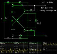
It is feasible to reduce supply level, by charging capacitors in series, then discharging them in parallel.

The problem is how to install switching devices in the proper manner, so they can be all the way On and all the way Off. Eight transistors or mosfets are needed. (Or maybe just 7 if a common ground is acceptable.)

Here is my best effort.


It is clumsy. It has a high parts count. And notice it still has the spikey waveforms.

I only wish someone might say "I'll market that because it doesn't need a coil", and make a million dollars, and cut me in for 1/10 of the profit.

Instead it is more practical to make a switched-coil buck converter. Coils have their own set of problems, but there are gains to be made by those who figure out how to work through them.
 
If you don't have an inductor and put the PWM signal directly into a capacitor, then the voltage drop from the input supply to the output voltage will be across the intrinsic resistance in the circuit (primarily the ON resistance of the transistor switch) and the efficiency will be no better than a linear regulator. You must have an inductor to store the energy from the PWM signal and transfer it to a lower voltage without power loss to gain the efficiency advantage that a switching regulator normally provides.

Thanks for wonderful information

- - - Updated - - -

The tendency will be for a capacitor to charge quickly to the supply voltage. The sudden current flow creates strong spikes which are troublesome.

It is feasible to reduce supply level, by charging capacitors in series, then discharging them in parallel.

The problem is how to install switching devices in the proper manner, so they can be all the way On and all the way Off. Eight transistors or mosfets are needed. (Or maybe just 7 if a common ground is acceptable.)

Here is my best effort.


It is clumsy. It has a high parts count. And notice it still has the spikey waveforms.

I only wish someone might say "I'll market that because it doesn't need a coil", and make a million dollars, and cut me in for 1/10 of the profit.

Instead it is more practical to make a switched-coil buck converter. Coils have their own set of problems, but there are gains to be made by those who figure out how to work through them.

Really appreciated...you design will try it..

- - - Updated - - -

I have calculated the Inductor values Required for my purpose, but what if i need variable SMPS ? which inductor value should i prefer ? the value which i got with min output voltage or the one with Maximum output voltage ? i've seen some DC Buck Converter's with Variable pot to get variable output....Inductor remains the same.
 

It is feasible to reduce supply level, by charging capacitors in series, then discharging them in parallel.

The technique is usually designated charge pump or switched capacitor voltage converter. Aprt from practical difficulties, that are already addressed in your post, a principle limitation is that a "lossless" conversion is only possible for rational voltage ratios. The fractional option is implemented with SC converters like LM3350 and LM3351, but only for low power.

Thinking about SC converter implementaion, you'll surely find out that it's best with MOSFET switches.
 

what value of inductor ? i will use to Switch from 1.8Volt or 2 Volt to 24 Volt ? I have 24Volt 15Amp Input. i need to make BUCK SMPS for digital voltage control. Please guide me so i will purchase the inductor accordingly...is there any calculator ?
 

what value of inductor ? i will use to Switch from 1.8Volt or 2 Volt to 24 Volt ? I have 24Volt 15Amp Input. i need to make BUCK SMPS for digital voltage control. Please guide me so i will purchase the inductor accordingly...is there any calculator ?
This should do what you want.
 
  • Like
Reactions: asking

    asking

    Points: 2
    Helpful Answer Positive Rating
Your coil can have a wide range of Henry values.

Suppose you purchase one between 100 uH and 1 mH (typical range). You will adjust the frequency and duty cycle to achieve 2V at your load.
At a duty cycle of 5% you will get maybe 1 V output.
At a duty cycle of 95% you will get maybe 23 V output.

You must use a coil which is rated for the maximum expected current. If you draw peaks of 15A from your supply, then your coil should be rated to handle that much without saturating, or overheating.
 
  • Like
Reactions: asking

    asking

    Points: 2
    Helpful Answer Positive Rating
But..what if i want variable power supply switching unit ? which inductor value i will select ?
You select an inductor for the highest current load you want.
The inductor can be larger than the indicated inductance value but should not be smaller.
 
  • Like
Reactions: asking

    asking

    Points: 2
    Helpful Answer Positive Rating
in this calculator what should i write for :

Inductor Current Ripple: ?
Output Voltage Ripple: ?

How much % ? i m confused please help

Inductor current ripple... The aim is to limit current so it never goes above the coil's saturation rating. For heavy loads a smaller ripple current (10 to 50 percent, continuous conduction mode) is advised because it puts less stress on components.
A light load can have greater ripple current (50 to 90 percent), or be in discontinuous conduction mode (DCM, 100 percent).

Output Voltage Ripple... This depends on how much variation in supply V your load can tolerate.
Your post #7 states it is a digital voltage control at 1.8 or 2V. Will ripple in its supply V show up as variations in its output? Choose accordingly.

- - - Updated - - -

Perhaps the chief spec you are interested in is cost of the coil. The smaller the Henry value, the less it costs.
The smaller the current it needs to carry, the less it costs.

Try various figures in the calculator, and see what coil sizes it comes up with.

Another spec is the capacitor value. The greater the load, the more uF you need. The less your output ripple tolerance, the more uF you need.
 

Status
Not open for further replies.

Part and Inventory Search

Welcome to EDABoard.com

Sponsor

Back
Top