electro13
Junior Member level 2

- Joined
- Nov 4, 2012
- Messages
- 23
- Helped
- 0
- Reputation
- 0
- Reaction score
- 0
- Trophy points
- 1,281
- Activity points
- 1,453
Hi all,
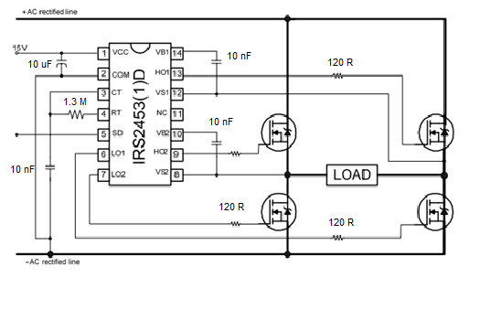
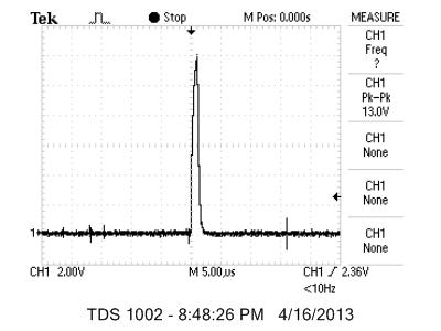
I'm trying to invert 230V dc i have from a DC-DC converter to a modified sine wave, im using IRS2453D to drive the bridge, I need the output to be at 50Hz, so according to the equation they have in the datasheet page 13 I calculated the RT, with CT being 10 nF, the problem im having is that theres no pulsing at the output of the chip, I only get a spike when it turn it on and no PWM, Ive tried different values for RT and CT to match those on the graph provided in the datasheet but with the same result,
Ive attached the schematic and the spike, and the link to the datasheet
Please I need help with this
thanks!!