Continue to Site

Welcome to EDAboard.com

Welcome to our site! EDAboard.com is an international Electronics Discussion Forum focused on EDA software, circuits, schematics, books, theory, papers, asic, pld, 8051, DSP, Network, RF, Analog Design, PCB, Service Manuals... and a whole lot more! To participate you need to register. Registration is free. Click here to register now.

IRS2330 Shoot Through Problem

Status
Not open for further replies.

chinuhark

Member level 5
Member level 5
Joined
Aug 16, 2014
Messages
88
Helped
1
Reputation
2
Reaction score
1
Trophy points
8
Visit site
Activity points
1,051
I'm making an SPWM based VFD using an Arduino. H1, H2 and H3 signals are generated by the Arduino and L1, L2 and L3 are obtained through 3 NOT GATES. Everything is fine upto this point. These signals pass through digital isolators ISO7220 and then go to a 3ph full bridge IRS2330 driver IC. The outputs of this are messed up.
First of all, I AM USING 4 ISOLATED 12V DC SUPPLIES AND NOT BOOTSTRAPPING if that may be the issue. I tested using a DSO as well as LEDs. H1, L1, L2 and L3 are as they should be. But H2 and H3 remain on for many PWM cycles many a times which would lead to shoot through.
To be sure, I slowed everything down. I used digital out from the microcontroller to get 3 square waves (Time period 1 second) on all 3 outs and observed on LEDs. The same thing happens. H2 or H3 or sometimes both remain stuck on high for a few seconds every once a while which would lead to H2 and L2 (or H3 and L3) to remain on together.
I don't want to go the bootstrapping route. What could be the problem.
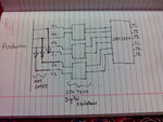
EDA.jpg

This is the issue. It works fine for a while but every now and then this happens. The problem is in H2, H3 where they remain stuck on high for a while.....
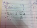
IMG_20140831_223258.jpg
 

The shown waveforms seem to indicate a IR2330 malfunction because the driver has shoot through protection which would never allow HS and LS outputs of a channel active at a time.

Regarding bootstrap versus isolated supply, IR2230 is still a level shifting driver which requires Vs1,2,3 >= Vs0. But the condition should be always fullfilled in a regular three-phase bridge.

To take full advantage from the isolated high side power supply you should consider separate couplers and drivers for the HS, I think.
 

Thank You FvM. I have good news and bad news.
Good news: You were right about the IRS2330 malfunctioning and things were perfect when I replaced it with a spare IRS2332 I had. I obtained absolutely perfect waveforms for all 6 gates, perfectly complementary with a deadtime of 1usec (checked using a DSO)

Note: As I get the gate signals (H1,H2,H3) from the arduino and use a NOT gate IC 7404 (for L1,L2,L3) there is initially no dead time. For dead time I completely rely on the driver IC IRS2332.

Bad news: I ran the inverter on no load and slowly increased the input ac voltage. Things were fine for the first 10 minutes or so and I was at around 150V on the DC link at this point. Then suddenly boom. One of the legs blew with both of it's IGBTs destroyed.

Now I am totally in the dark as to how to identify the cause.

Questions:
1) Can something like this happen if and only if there was no dead time or overlapping of the gate signals as the inverter was on no load, i.e. can I assume that the issue was in the gate signals and had nothing to do with the power circuit (as it was on no load). Or can this happen even if the control signals were fine?

2) Assuming that the issue was in the control signals, can the issue be the IRS2332 and is it unsafe to rely solely on it to generate dead time? Datasheet gives the deadtime as - 0.5us min, 0.7us typical, 1.1us max.

So what do you guys think went wrong?
 

Bump!
Someone please help me as to why my driver ICs are malfunctioning?
I checked the pulses for the IRS2332 which replaced the earlier broken IRS2330 and it's H1,H2,H3 are fully stuck on HIGH.
Everything was working perfectly upto 150Volts on the DC bus for 10min or so and then there was a shoot through which blew up the 1st leg.
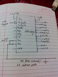
This is how I have connected them. Is there something wrong here that is damaging the HVICs?

2330 ckt.jpg

Details:
Vss and Vso are shorted and the same ground is used for the control and power ckt, i.e. connected to DC bus
Fault, ITRIP, CAO and CA are not connected
A,B,C,D indicate isolated supplies
A total of 4 supplies are used,
A - Logic, Low side
B,C,D - for H1, H2, H3 respectively
All supplies are 12v regulated
0.1uF decoupling caps are connected for each as close to the IC as possible
 

Status
Not open for further replies.

Similar threads

Part and Inventory Search

Welcome to EDABoard.com

Sponsor

Back
Top