Continue to Site

Welcome to EDAboard.com

Welcome to our site! EDAboard.com is an international Electronics Discussion Forum focused on EDA software, circuits, schematics, books, theory, papers, asic, pld, 8051, DSP, Network, RF, Analog Design, PCB, Service Manuals... and a whole lot more! To participate you need to register. Registration is free. Click here to register now.

IRS2330/IR2110 gate resistor calculation

Status
Not open for further replies.

chinuhark

Member level 5
Joined
Aug 16, 2014
Messages
88
Helped
1
Reputation
2
Reaction score
1
Trophy points
8
Activity points
1,051
I am using an IRS2330 3ph Bridge driver with FGA25N120 IGBTs. (No bootstrapping, 4 isolated supplies at the moment) I am confused and have searched a lot as to how the value for Rg, i.e. resistance between the HI/LO out and the gate is calculated, both value and power rating. At first thought, I thought since the IRS2330 is rated for 200mA, it will simply be 12V/200mA or 60 Ohms, but that's too high and obviously wrong. Then I realized that as the current will be decaying with time, its not going to draw constant 200mA current. Now I couldn't find a value for peak current for IRS2330, which I think would be correct (V/Ipeak = R), not sure though.
1) So what's the actual method to find Rg (magnitude and Power Rating)
2) Also please give the method for calculating Rgs (mag and Power Rating)
3) Is it OK to simply connect anti-parallel diode with Rg? Wouldn't that make RgOFF zero and cause huge discharge current during turn off? Any other problems on IGBT side due to very quick turn off? If fine, Is 1N4148 OK?
 

Rg magnitude affects turn-on/off times [ns] and switch losses [mJ] and one chooses deadtime in bridges from diode, R and Rg differential rise times, so Rg value is selected from spec charts >=5 , with 10 suggested in specs.

Decide on shoothru time avoidance or deadband from slow Tr and fast Tf usng low inductance diode and, low ESL power connections. 1n4148 may be marginal for power, but check for resonance from Leads and reverse recovery time.

IMG_1133.JPG

Input capacitance depends on Vce and thus Vgs.
Rg power is thus P=I²Rg* Tduration , where Tduration is the repetition rate , f of gate discharge time constant (RgCiss) and Ipk=Vgs / Rg.

I think, then, P=Vg²/2Rg * RgCiss *f, where 1/2 is using the triangle area approximation of Ipk thus the power becomes P=½CissVg²*f

for 1MHz,the powerin Rg appears to be less than 1/2W , pls verify.
 
Rg magnitude affects turn-on/off times [ns] and switch losses [mJ] and one chooses deadtime in bridges from diode, R and Rg differential rise times
This I understood. Also would like to mention that I don't need any extra Dead Time as the IC IRS2330 has fixed deadtime of 2us by default.
so Rg value is selected from spec charts >=5 , with 10 suggested in specs.
This....Not so much. How does one simply 'choose' the Rg value. Doesn't the current supplying capacity of the Driver IC play any role?

Rest of the stuff, including symbols in the equations, I am sorry but, couldn't understand much. Could you suggest a book or App Note or PDF where I can find all this?
 

Someone please help...Everywhere I read, people say use any value of Rg btn 10E to 33E. Where does this come from? If it's upto choice, I don't understand why anyone would select a value greater than 10E, as higher the value of Rg, higher will be the switching losses.
1) The only current rating I could find for IRS2330 is 200mA, which Digikey says is the peak. This puts Rg=Vgs/Ipk = 12/0.2 = 60 Ohms. Can it be that high? I am beginning to think it can as IR2110 has a rating of 2A which would put it's Rgmin at 6 Ohms. (Please verify!)
As far as power, I think I understood your calculations, and so I think it is a non-issue. Quarter watt will be easily sufficient in almost all cases as f cannot be great than 20kHz, at least for me(Please Verify!).
2) How can I directly connect 1N4148 which has a Peak current rating of 2A. During discharge, if there is no resistor to limit the current, wouldn't the peak definitely be greater than 2A? And the discharge current rating of the driver is even less at just 420mA. Assuming that this is also the peak rating, Roff cannot be less than 28 Ohms (Please verify!). Again without thinking much, I will use quarter watt.
3) How much Rg is already present internally in the driver and IGBT as I will obviously have to subtract that from calculated values...
4) How will I get the stray inductance value to check the condition Rgmin > sqrt(Ls/Ciss)?
 

This I understood. Also would like to mention that I don't need any extra Dead Time as the IC IRS2330 has fixed deadtime of 2us by default.

That deadtime is 2000ns typ and ranges from 1300 to 3100ns and ONLY controls the driver pulse deadtime, which is not the same as the IGBT output deadtime since Rise and fall time are not the same.

This is why diode is used in parallel with Rg to ensure Deadtime is not degraded.
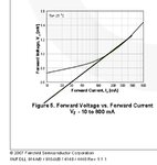
The diode represents an ESR of approx 2 Ohms above the knee. Many factors determine final selection of Rg network for optimal control of IGBT. THis complexity is a tradeoff for margin to thermal runaway at max inductive load and worst case deadtime.
1n4148.jpg
Specs for Rg min is based on current limit for Ig. The HVIC is limited to -250mA , +500mA typical ( Not worst case ) for Io. Rg min of 5~6 Ohms is shown in graph, 10 is used in specs for a reason.
 

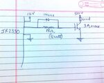
IMG_20140817_125526.jpg
So is this fine?
I still have a tiny issue about the fact that It is the same resistor being used for IR2110 rated at +2A, -2A and the IRS2330 rated at at +200mA,-420mA.
 

The HVIC's are not current sources but rather current limited switches. The pulsed short circuit current spec of 2A is based on a 15V supply and implies the RdsOn is 7.5Ω.

This article from Fairchild explains more factors and details on Rg.
 

SunnySkyguy,
Firstly the App note is amazing.
I sent an email to IR tech support and they said that 200mA is the peak value. This is really confusing me a lot now. Everyone I've consulted including you and my teacher are of the opinion that Rg = 60 Ohm is too high a value for Rg. Now am I missing something here? Wouldn't Rg<60 Ohm lead to Ipk>200mA.
The appnote says, 'If the Gate drive does not have enough power, Rg becomes meaningless'. My interpretation of this is that this is the case here. Please share your thoughts.
 

Frankly I too am confused why gate current is so low yet they graph Rg from 5 to 90 Ohms with +/-15V in the spec.

I would switch exclusively to Diodes Inc. IMHO , they make better parts.
Igt.jpg

Here is a spreadsheet from Diodes Inc (Zetex)for computing rise fall times and power switch dissipation... They don't even worry about Gate current as they are built for much higher gate current. **broken link removed** There is an optimum value of Rg which you can find for switching times and Rds power dissipation in the spreadsheet by trial and error by adjusting Rg.

Here is a shorter one from Microchip https://ww1.microchip.com/downloads/en/DeviceDoc/mosdrvrs.xls

I would switch FETs or use 10 to 22 Ohms if you must (!) use the same FETs.

I would choose a MOSFET about 100~200x lower than the driver RdsOn as a rule of thumb, which is like choose transistor gain of 200x.
 

Thanks for your support. These 2 days I've learned a lot about IGBTs, MOSFETs and driving them.
I sent another mail to Tech support regarding the internal resistance in the driver if any so as to subtract that from calculated value, and the reply was that their internal MOSFETs have an Rdson of 60 Ohms which probably limits short ckt current from exceeding around 200-250mA.
She also said that the external resistance will be an extra Rg.
I have finally concluded that the external resistor is to be connected as close to the gate and it's aim is purely damping the oscillations due to stray inductance (and maybe other factors which I may not have studied yet).
So I think in this ckt I am going for 10-20 Ohms as the PCB is already printed. Next time on, I am actually considering 3 IR2010s or making my own totem pole driver for 2 reasons: a) No issue whatsoever as far as Ig is concerned b) I have a feeling that it may be a cheaper option (Not sure, but it's possible).
I'm currently researching Driver ICs vs discrete totempole drivers, but haven't found much yet.
 

Status
Not open for further replies.

Similar threads

Part and Inventory Search

Welcome to EDABoard.com

Sponsor

Back
Top