Continue to Site

Welcome to EDAboard.com

Welcome to our site! EDAboard.com is an international Electronics Discussion Forum focused on EDA software, circuits, schematics, books, theory, papers, asic, pld, 8051, DSP, Network, RF, Analog Design, PCB, Service Manuals... and a whole lot more! To participate you need to register. Registration is free. Click here to register now.

IRF3205 burning at only 25 Amper

Status
Not open for further replies.

anotherbrick

Full Member level 4
Full Member level 4
Joined
Jan 10, 2009
Messages
222
Helped
1
Reputation
2
Reaction score
1
Trophy points
1,298
Location
Istanbul , Turkey
Visit site
Activity points
3,190
hello dear Forum ,

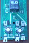
I am sending 2 photos ( up and downside )of my circuit
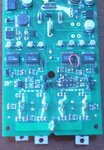
üst.jpg
alt.jpg

I have 2x H bridges with IRF3205
as you can see the 24V is entering the circuit beside the relay
and GND is entering at the bottom of the circuit

I am driving electric wheelchair motors
I am measuring the current into H bridge with ACS7xx sensor and if it is more than 25 Amps
I am decreasing the PWM duty

as you can see one of the H bridges is burned ( I have cut the IRF3205s and ACS7xx)

I am using IR2113 to drive the FETs
the accu voltage is 24 V - the gate voltage is 12 V with LM2575-12
at the output of IR2113 there is 22Ohm to the gate
and parallel to 22 Ohm a 1N4148 direction to the IR2113
i.e cutting off FET faster than turning on

what can you say to me ?
is there a layout problem ?
can the IRF3205 be fake ?

please advice

thank you

note : I forgot to say the FETS are cooled with enough aluminium case
 

Re: help! IRF3205 burning at only 25 Amper

as you can see the 24V is entering the circuit beside the relay
and GND is entering at the bottom of the circuit

Actually, we can't see that, but we'll take your word for it. A schematic would help a lot more than a picture.

Do you have flyback diodes to protect your MOSFETS? Are the MOSFETs overheating, or are they being damaged by inductive kickback?
 
Re: help! IRF3205 burning at only 25 Amper

there are freewheeling diodes inside IRF3205s
the mosfets are cooled by the aluminium case of the device ( of course galvanic isolated ( not shown above )
there is no coooling problem - I cannot feel any warming of the aluminium case
the finished product is something like that

https://www.google.com.tr/search?q=...urce=og&sa=N&tab=wi&ei=1MqlUsarFMaM4ATNmIHYCw

or are they being damaged by inductive kickback?
I am asking the same question

the IR3205 according to datasheet can withstand 55 V and 110 ampers
but in my circuit I limit the current to 25 amperes
I am measuring the current with ACS714 and decrease the PWM duty if it is bigger than 25 amper

- - - Updated - - -

sema.JPG

the schematic

- - - Updated - - -

the component values are not real
 

Re: help! IRF3205 burning at only 25 Amper

I'm not sure, but I don't think the IR2113 has any shoot-through protection. In other words, if you inadvertently drive HIN and LIN both on, what will happen on the output?
 
Re: help! IRF3205 burning at only 25 Amper

Some 'scope photos of the 4 gate and 2 switch-nodes
would do more for you than any amount of speculation.
 
Re: help! IRF3205 burning at only 25 Amper

I also was thinking shoot-thru, or that the Mosfets are not being driven properly.

For troubleshooting H-bridges, you must monitor the gate drives of the top and bottom Mosfets simultaneously with an oscilloscope.
Since the top Mosfet is floating from ground, a differential probe is a required...no other way is possible.
 
Re: help! IRF3205 burning at only 25 Amper

schmitt trigger;1306017Since the top Mosfet is floating from ground said:
100% not true. Put one probe on the source, and one on the gate and subtract.
 
Re: help! IRF3205 burning at only 25 Amper

Barry: True only because it is operating from a low voltage source.

But the resulting waveform will be accurate only if the original poster has a 4 channel scope and the said channels are sampled synchronously.

But even then, if the two probes are not identically compensated, there will be artifacts in the subtraction.
 
Re: help! IRF3205 burning at only 25 Amper

24V.JPG
gates2.JPG

hello dear forum members

I have attached 2 scope photos
the one is the 24V ( scope AC coupling ) just at the entry of H bridge
you can see the spikes at turning ON and OFF point of high side mosfet
the yellow line is gate of high side mosfet

the second photo is the gate signals of high side and low side mosfet
yellow line is high side
blue line is low side
the spikes at the gate of low side mosfet triggered by the turning ON and OFF of high side mosfet
really bothered me - is this the problem ? what do you say ?

these are from left side of H bridge
the right - high side is OFF
and the right - low side is always ON

( the motor current is about 3 Amperes during the photos )
what do you advice ? any help appreciated
thank you
 

Re: help! IRF3205 burning at only 25 Amper

A few things:
1. Tell us a bit more about the circumstances of the failure. Was it right as the motor started up, or was suddenly braking, or just while driving continuously? Does the failure repeat itself?
2. Do you ensure that the duty cycle on H bridge is kept within resonable limits (like 10% to 90%)?
3. Those waveforms look fine to me. The spikes aren't very big and may just be the result of emi in the probe leads.
4. Do you normally use heatsinks for the FETs?
 
Re: help! IRF3205 burning at only 25 Amper

the answers

1) this circuit is the accu wheelchair joystcik control circuit - I used it several days ( about 10 days x 20 minutes ) with the wheelchair - ( I forced it against the wall I mean I used it before with 23 amperes ) and at the last day I climbed a 5 meter ramp - the motor ( each of left and right ) current during climbing was about 23 amperes ( I know becouse I limit the PWM duty in order to limit the motor current to 23 amperes ) after I climbed the ramp I tried to drive the chair on the flat street - just at this time the current sensor at the entry of H bridge of left motor blow up with smoke - when I measured the mosfets I saw the left side of left motor H bridge ( one leg) was blown - it was first failure with IRF3205 , before I used IRF540 and the failure happened before 2 times when I decided to use current sensor to limit the PWM duty
2) the duty of the PWM was %45 when the circuit burned - the duty is increasing from 0 to %45 with a ramp when pushing the joystick
3) I didnot measured these photos with 20-25 amperes becouse I am afraid it will blow up again - these waweforms with current 3 amperes
4) there are enough aluminium heatsinks - I checked the tempereture after the burning it was not even warm
 

Re: help! IRF3205 burning at only 25 Amper

Just because the heatsinks weren't hot after the failure, doesn't mean that they didn't contribute to the failure. How are the FETs fixed to the aluminum, and how are they insulated? Can you show a good photo of the heatsink surface after the failure? Often if there's an insulation failure with the heatsink, the damage left behind will show it.

As for the gate waveforms, you should try looking at them close to full load. But judging from those waveforms it looks like you insert a lot of dead time (looks like maybe 1us). Keep in mind that excessive dead time can be dangerous as well. Probing the bridge output would be helpful too.
 
Re: help! IRF3205 burning at only 25 Amper

4) there are enough aluminium heatsinks - I checked the tempereture after the burning it was not even warm

A cool heatsink can be a bad thing, especially if you expect it to get rid of quite a bit of heat. You are looking to get rid of 24W plus whathever is lost during transition (which can be quite a lot, too). So if your heatsink is not warm, that heat is staying right where it is: in the FET...
 
Re: help! IRF3205 burning at only 25 Amper

24V-2.JPG
gates3.JPG

hello dear forum members,

I checked the gate waveforms with about 25 Amperes load current
it didnot change much

however the 24 V at the entry of H- bridge
please comment on the spikes at turning ON point of mosfet
as you can see there is about 20 V spike + 24 V of accu = 44 V

the IRF3205 is 55 V max
can the problem be this ? how rigid is the mosfet against voltage spikes ?
if the voltage reach 55 V for microsecond does the mosfet fail immediately ?

2) the mosfets are screwed tight with steel bar against alu block with teflon isolation
the screw is isolated too with plastic "thing" - sorry this is my best english
the case is in the factory sorry no photo
I checked after the original failure with ohmmeter against short circuit of alu case with transistors
the insulation was OK
 

Re: help! IRF3205 burning at only 25 Amper

View attachment 100129
View attachment 100130

hello dear forum members,

I checked the gate waveforms with about 25 Amperes load current
it didnot change much

however the 24 V at the entry of H- bridge
please comment on the spikes at turning ON point of mosfet
as you can see there is about 20 V spike + 24 V of accu = 44 V

the IRF3205 is 55 V max
can the problem be this ? how rigid is the mosfet against voltage spikes ?
if the voltage reach 55 V for microsecond does the mosfet fail immediately ?
Well first of all, I'd have to see exactly how you did the measurement to be convinced that those spikes actually exist on the 24V line, and aren't caused by EMI. Try just probing circuit ground near the H bridge and you'll likely see those spikes. If so they're just EMI and shouldn't be a problem. If the spikes are really on the 24V rail, then you either have to add some high frequency bypass caps to the rail, or improve the layout to reduce parasitic inductance, or add RC snubbers (or a combination of these things).
2) the mosfets are screwed tight with steel bar against alu block with teflon isolation
the screw is isolated too with plastic "thing" - sorry this is my best english
the case is in the factory sorry no photo
I checked after the original failure with ohmmeter against short circuit of alu case with transistors
the insulation was OK
Teflon?? Teflon is a terrible thermal interface material. How thick is it?
 
Re: help! IRF3205 burning at only 25 Amper

Teflon?? Teflon is a terrible thermal interface material. How thick is it?

Perhaps he´s referring to Mica material.


+++
 
Re: help! IRF3205 burning at only 25 Amper

I have one question

If the VDS voltage limit of 55 V is exceeded for milisecond due to inductances
does the MOSFET immediately fail ?
 

Re: help! IRF3205 burning at only 25 Amper

The mosfet will go into avalanche mode.
Most mosfet are perfectly capable of absorbing single, low energy pulses.

However, repetitive or high energy pulses are another story.
 
Re: help! IRF3205 burning at only 25 Amper

The mosfet will go into avalanche mode.
Most mosfet are perfectly capable of absorbing single, low energy pulses.

However, repetitive or high energy pulses are another story.
----------------
@chaitanya
Add snubbers yout problem will solved

the spikes are repetitive but I dont know if they are high energy

https://www.littelfuse.com/~/media/.../Littelfuse_TVS_Diode_1_5KE_Datasheet.pdf.pdf

can I use this product to protect MOSFETS ?
must I use uni- or bi-directional ?
must I use 1 for each MOSFET ?
where to the MOSFETs do I have to connect this ?

thank you
 

Status
Not open for further replies.

Similar threads

Part and Inventory Search

Welcome to EDABoard.com

Sponsor

Back
Top