- Joined
- Jan 22, 2008
- Messages
- 52,427
- Helped
- 14,752
- Reputation
- 29,786
- Reaction score
- 14,105
- Trophy points
- 1,393
- Location
- Bochum, Germany
- Activity points
- 298,127
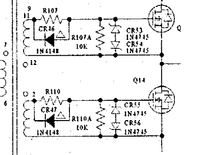
1N4148 where? We never saw a complete schematic yet.one more thing,i used 1n4148 diode.will it be fine or use other one?