Continue to Site

Welcome to EDAboard.com

Welcome to our site! EDAboard.com is an international Electronics Discussion Forum focused on EDA software, circuits, schematics, books, theory, papers, asic, pld, 8051, DSP, Network, RF, Analog Design, PCB, Service Manuals... and a whole lot more! To participate you need to register. Registration is free. Click here to register now.

IR2153 bomb the fuse

Status
Not open for further replies.

hamid159

Full Member level 3
Joined
Aug 25, 2013
Messages
176
Helped
14
Reputation
28
Reaction score
14
Trophy points
1,298
Location
Lahore
Activity points
2,488
IR2153 circuit problem

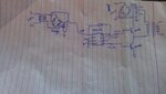
hy guyz,i'm in a big trouble.i have made a smps circuit using ir2153.whenever I power on the circuit...fuse breaks down.i analyze the circuit many times...I think may be ground is causing problem.....please help me.i have attached my circuit diagram
 

Attachments

  • IMAG0832.jpg
    IMAG0832.jpg
    1.5 MB · Views: 266

The circuit sounds like the concept of blending two different topologies in a single implementation: The two transistors are arranged as if they were HALF-BRIDGE, but the connection to the transformer seems trying to perform a topology PUSH-PULL.

Furthermore, the power passing through the capacitor, did not really understand.


+++
 

According to the datasheet, there should be a connection from the VS pin on the IR2153 to the mid-point between the 2 MOSFETs.
 

i have missed it in making the diagram..but actually I made this connection.
 

According to circuit drawn, connecting VS to transformer center-tap as you mentioned above, were polarized reversely the transistor driven by HO output.


+++
 

The circuit is correct, except for 17 V driver supply. Must be < 15.6 according to IR2153 datasheet.
 

FvM,


He selected the topology Push-Pull, on which these transistors should be placed oppositely one to another ( common drain ).
But according to schematic, seems to be not this way, correct ?

fet.JPG

+++
 

It looks like a normal half bridge implementation to me. A push pull would require a centertapped primary.

There's nothing really wrong with the schematic as shown (except for admissions already pointed out), though I suspect that seeing the full schematic, along with component values would reveal a problem. For example if the secondary of the transformer is unloaded and you are driving the primary circuit at resonance, it can be expected do draw massive current.
 

It looks like a normal half bridge implementation to me. A push pull would require a centertapped primary.

But there are a bus supply connected on middle of both transistors.

According to the datasheet, there should be a connection from the VS pin on the IR2153 to the mid-point between the 2 MOSFETs.

It´s a real mess, due I also understood this topology as a Push-Pull, instead a Half-Bridge.
I guess we cannot give to him proper tips unless redrawing above draft schematics.


+++
 

But there are a bus supply connected on middle of both transistors.
No there isn't. "middle of both transistors" is connected to primary of output transformer. Other side of transformer primary is connected to ground through a capacitor.
 

Yes...you are totally right about to the circuit topology.
The draft posted induced to misunderstanding, at least to me.


+++
 

now I have tried the same circuit with sg3525 and ir2110..again same problem...I'm not getting what is actually wrong with it.ir2110 was giving correct output on no load (without applying 300V dc ) .frequency was set to be 65kHz.whenever I power on the circuit....mosfets get shorted :-(
 

Are you providing proper dead time to prevent simultaneous conduction of both transistors ?
This is necessary to avoid these devices performing short-circuit on power bus to ground.


+++
 

The problem with IR2153 doesn't suggest shoot-through problems, because the driver has sufficient built-in deadtime.

A possible problem is exceeding diode commutation dv/dt with inductive loads. In this case, increased gate resistors or preferably fast-off/slow-on RD combinations can help. Or using modern MOSFETs with fast reverse diode. They are available in the 600 V class.
 

According to the schematic, the high voltage resevoir consists of two 27nF capacitors connected in series. That can't be right, can it? Maybe they're supposed to be 27uF? That would give about 60V pk-pk ripple with 100mA current draw from the 300V line.

Why are those capacitors connected like that anyway? I appreciate it could work, but wouldn't it make more sense to use one cap for the high voltage resevoir, and another to couple the transformer primaryto ground? At least then their values could be chosen independently.
 

...frequency was set to be 65kHz.whenever I power on the circuit...

Switching some device at this frequency without employing some snubber circuit seems prone to failure, due to massive dv/dt that FvM already mentioned.


+++
 

The capacitors may form a series resonant circuit with transformer leakage inductance.
 

Maybe I'm missing something here but I don't see ant current limiting, current sensing, or soft start in that circuit.

Assuming there's a rectifier and resevoir capacitor connected to the transformer secondary, what happens at switch on? Does it just start switching with a 50% duty cycle and attempt to instantly charge the resevoir cap? Surely that can be expected to cause massive over-current?

Or is there something more elaborate connected to the transformer secondary? I suspect the reason for the failure may be related to whatever's connected to the output (and not shown in the schematic).

Disclaimer: I'm far from a boffin when it comes to SMPS.
 

I think if the problem is due to absence of snubber circuit then atleast mosfets shouldn't burn at no time...they should get hot and then burn up.shouldn't it? I have noticed that in case of sg3525 and ir2110,,,i apply 5V at vdd pin through 7805.when I measure the voltage at vdd pin of ir2110...It comes to be 11V..is this not nonsense?

- - - Updated - - -

I connected the rectifier and capacitor....even I couldn't check the input capacitor voltage.because mosfets get shorted....and the capacitors discharged rapidly due to short circuit.

- - - Updated - - -

one more thing,i used 1n4148 diode.will it be fine or use other one?
 
Last edited:

please guyz help me.... I have damaged a couple of mosfets..I've tried the circuit with tl494,sg3525,tc4424,ir2153 but all times the same problem... :-( :-( :-(.This is the waveform present on both half bridge mosfets...but when I apply 300V,,,mosfets get shorted and also fuse disconnects.
 

Attachments

  • IMAG0881.jpg
    IMAG0881.jpg
    939.1 KB · Views: 63
Last edited:

Status
Not open for further replies.

Similar threads

Part and Inventory Search

Welcome to EDABoard.com

Sponsor

Back
Top