Continue to Site

Welcome to EDAboard.com

Welcome to our site! EDAboard.com is an international Electronics Discussion Forum focused on EDA software, circuits, schematics, books, theory, papers, asic, pld, 8051, DSP, Network, RF, Analog Design, PCB, Service Manuals... and a whole lot more! To participate you need to register. Registration is free. Click here to register now.

Ir2110 circuit issue

Status
Not open for further replies.

Benn Ng

Newbie level 6
Joined
Mar 25, 2015
Messages
11
Helped
0
Reputation
0
Reaction score
0
Trophy points
1
Activity points
103
hi guys,

reading up this forum i still encounter this problem, please advise.

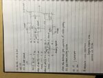
circuit as attached.

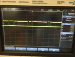
the signal high and low logic is being fed out an output from the optocoupler with frequency 32khz and vpeak of 6.2V. i want to test the output of the HO and LO of ir2110 to see what the voltage but i could not see any signal being output? being its is fed into the mosfet gate.

do i need to put a full bridge circuit to test the gate signal that is produce? or i can just test by using a scope directly pluck at pin7 and pin of ir2110 to see the waveform. no signal is being detected currently. please advise thanks you

regards
 

Attachments

  • IMG_1087.JPG
    IMG_1087.JPG
    1.9 MB · Views: 106

Hi,

optocouplers are often open collector outputs.
Did you use a pullup/pulldown resistor?

Measure with a scope all signals. Follow the signal from your square wave generator to optocoupler input, optocoupler output, driver input, driver output, fet gate, halfbridge output.
Then you will see where you loose the signal.

Klaus
 

hi, yes i used a pull up resistor from 5V to 350ohm, based on datasheet.


square wave generator output is sqaure wave with 32khz @5.2v peak
output of optocoupler is sqaure wave with 32khz @6V peak which is the input of the driver.

but the driver output is nothing when i scope over the gate of the fet.

do i need to connect a load to the output (HO - pin7 / LO pin1) to a half bridge or can i just scope over the 2 pin directly?
 

Attachments

  • outputofopto.JPG
    outputofopto.JPG
    2.1 MB · Views: 78

LO should show an output signal without further requirements except for correct Vdd and Vcc supply, SD = low. HO gives only an output signal if the external circuit allows charging of bootstrap capacitor, e.g. Vs grounded.
 

The output of optocoupler v peak is 6.2v
The output of lo pin1 is tested to be 24v with 32khz but the pin7 ho is not giving anything.
The circuit is not loaded with any motor.

As mention by U. Ho only give output of the same v peak like lo (pin1) just that is opposite of each other?

Able to give a schematic to how do I allow charging of the capacitor ? Like vs is grounded?
 

The normal way to get output from highside driver is connect output transistors and apply a suitable input wavefom that periodically activates the low side and thus charges the bootstrap capacitor.

Grounding VS (shorting VS and COM) can be a workaround to test the driver circuit on it's own. If you don't understand why, you're supposed to spend quite a little time reading the application notes about bootstrap driver operation principles.
 

Status
Not open for further replies.

Part and Inventory Search

Welcome to EDABoard.com

Sponsor

Back
Top