Continue to Site

Welcome to EDAboard.com

Welcome to our site! EDAboard.com is an international Electronics Discussion Forum focused on EDA software, circuits, schematics, books, theory, papers, asic, pld, 8051, DSP, Network, RF, Analog Design, PCB, Service Manuals... and a whole lot more! To participate you need to register. Registration is free. Click here to register now.

ir2110 bootstrap capacitor calculation

Status
Not open for further replies.
Hello
I am trying to build 3 phase inverter using pic18f4431 mcu, pwm frequency =16khz
Power circuit consist ir2110 mosfet driver, irf 840 as switching device.
I am facing problem while calculate bootstrap capacitor value.
VDD=5VOLTS, VCC=12VOLT, DC BUS VOLTAGE=342
Please any one suggest me what should be right value for bootstrap capacitor. I shall be very thankful.

i can give u equations and how to find that out , but i will talk too much and it has been asked 1million times before .

So my recommendation for this circuit use 1uF cermaic rated to above bus voltage example 400v

hope this helps :-D
 
  • Like
Reactions: abc_de

    abc_de

    Points: 2
    Helpful Answer Positive Rating
Hello
Yes I have an equation for bootstrap capacitor calculation but many of parameters are out of my mind. :thinker:
Presently I am using 3.3uf/63volt and its working fine.
You mean I have to use 1uf/400volt ??? is 63volts is low value of capacitor.
 

The voltage across bootstrap capacitor does not exceed Vcc voltage (12V typically) so 63V is safe enough. If you're using an electrolytic capacitor (3.3uF) then it's better to put a ceramic one (0.1uF) in parallel.
 

Hello
Yes I have an equation for bootstrap capacitor calculation but many of parameters are out of my mind. :thinker:
Presently I am using 3.3uf/63volt and its working fine.
You mean I have to use 1uf/400volt ??? is 63volts is low value of capacitor.

sorry i meant 40v . i should be higher than Vcc not vbus ,
 
  • Like
Reactions: abc_de

    abc_de

    Points: 2
    Helpful Answer Positive Rating
hello
red_alert and all
i had follow the spwm technique for single pahse inverter.
please suggest me i am going right or any suggestion for improvement


https://obrazki.elektroda.pl/7991531500_1424017629.jpg
https://obrazki.elektroda.pl/1229176100_1424017631.png
https://obrazki.elektroda.pl/6458394000_1424017632.png

- - - Updated - - -

i am following the unipolar_spwm.jpg

- - - Updated - - -

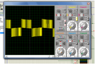
waveform.jpg
these are output wave forms

- - - Updated - - -

output unipolar spwm.pngspwm channel output.png
 

The wave forms look OK (though they're pretty unclear).

Anyway, you have to check that while one low-side switch is kept in the ON state, the other leg high-side switch is following the sine PWM signal (with an ascending then descending duty cycle) and the corresponding low-side switch is driven by a complementary signal (don't forget about dead times though).
 

hello
red_alert and all
i had follow the spwm technique for single pahse inverter.
please suggest me i am going right or any suggestion for improvement


https://obrazki.elektroda.pl/7991531500_1424017629.jpg
https://obrazki.elektroda.pl/1229176100_1424017631.png
https://obrazki.elektroda.pl/6458394000_1424017632.png

- - - Updated - - -

i am following the View attachment 114295

- - - Updated - - -

View attachment 114297
these are output wave forms

- - - Updated - - -

View attachment 114298View attachment 114299

these results are made by isis proteus right ? why donot u try orcad pspice simulation it is more accurate and realistic . otherwise the results seem normal , but u need to try the circuit and see real life measurments .
 

Status
Not open for further replies.

Similar threads

Part and Inventory Search

Welcome to EDABoard.com

Sponsor

Back
Top