Continue to Site
Follow along with the video below to see how to install our site as a web app on your home screen.
Note: This feature may not be available in some browsers.
Sorry for the late reply,Hi,
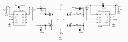
We don´t know:
* VIN
* IN1, IN2 , SD_Bar levels and duty cycle range
* R6 type
* PCB-layout
* which MOSFET becomes hot
* exact motor type
Klaus
Yes, Q1 and Q3 are heating. So, how can I control or generate enough deadtime?. Please guide meThe dead time supplied by 2104 is 650 nS at 1000 pf load.
Have you done a scope capture of actual timing looking at gates of
Q1 and Q3 ? Your deadtime may not be sufficient. Hopefully if thats
the case your PWM outputs allow you to also control and set additional
dead time.
This example shows 16 clocks of deadband (ph1 and ph2 as a result never on
at same time) -
View attachment 171024
Regards, Dana.
What is the HW/Processor/Part Number you are using to generate the PWM signal thatYes, Q1 and Q3 are heating. So, how can I control or generate enough deadtime?. Please guide me
processor is dsPIC30f4012What is the HW/Processor/Part Number you are using to generate the PWM signal that
drive the 2104's ?
Regards, Dana.
No, the VCC of the IR2104 is 15V this is the mistakeHi,
You say:
VIN = 24V ... but this is connected to VCC of the IR2104, which is rated for 20V only.
SD_BAR = 0V .. this means the driver is disabled.
What MOSFET type are you using? Link to datasheet.
What about your "secrets"? I guess you have your reason not to show them.
* IN2 information, complete
* IN1, IN2 voltage levels
* and all the other items.....
But without them it´s really hard to give useful help.
Klaus