Continue to Site

Welcome to EDAboard.com

Welcome to our site! EDAboard.com is an international Electronics Discussion Forum focused on EDA software, circuits, schematics, books, theory, papers, asic, pld, 8051, DSP, Network, RF, Analog Design, PCB, Service Manuals... and a whole lot more! To participate you need to register. Registration is free. Click here to register now.

ir remotr interface via microcontroller

Status
Not open for further replies.

abubaker-makki

Newbie level 1
Newbie level 1
Joined
Aug 7, 2014
Messages
1
Helped
0
Reputation
0
Reaction score
0
Trophy points
1
Visit site
Activity points
8
hi
i read the last post in IR remote and how any one make him remote and that is nice work
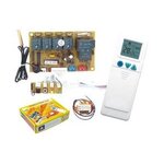
but i have an unit Universal a c control system qd-u03c+ Air conditioner pcboard qunda double sensors like the picture i want to know the frequency of remote transmit ? and i want to interface this remote via pic micro controller using micro c what can i do please ?
uo2b.jpg

thanks
 
Last edited:

Hi,

look at the devices. find out what transmitter chip or receiver chip is used.

Klaus
 

Hello!

The carrier frequency is almost always around 38 ~ 40 kHz.
As for the code themselves, there are many schemes which boils down to
2 types. Examples of what I have seen after analysis of all remote controls I had at home
(about 10 of them). Basically a remote controller maker:
- Can decide that one of the levels has always the same width of 1 (this "1" is a certain
fixed duration of a few 100s of microseconds, say around 1 ms), and then the other level has
a variable width. A width of 1 (same as above) means 0, and a width of 2 (twice of above)
means 1
- Can decide that your signal is a series of fixed period of 3 units. If you have 001, it
shall mean 0, and if you have 011, it shall mean 1.

Of course these 2 types can be used in reverse logic which makes you 4 types.

And from there it's quite easy to make a receiver that "sniffs" which kind of remote control
you have.

1. If the low level (high level in reverse logic) has always the same width, then you are one
case 1.
2. If the sum of one low and one high is always the same duration, you are in case 2.

Usually you get a pattern that repeats every xxx ms.

What I used:
That kind of receiver : https://www.cresttech.com.au/pdf/para/ReceiverModule.pdf
A MSP430 board.

What I made:
Use a timer to get the patterns
Sniff and process these patterns.

That's pretty basic programming but it's fun as an after-5 development.
I'm not sure this replies exactly to your question, but you get some guidelines to start.

Dora.
 

Status
Not open for further replies.

Similar threads

Part and Inventory Search

Welcome to EDABoard.com

Sponsor

Back
Top