Continue to Site

Welcome to EDAboard.com

Welcome to our site! EDAboard.com is an international Electronics Discussion Forum focused on EDA software, circuits, schematics, books, theory, papers, asic, pld, 8051, DSP, Network, RF, Analog Design, PCB, Service Manuals... and a whole lot more! To participate you need to register. Registration is free. Click here to register now.

IR Jammer Circuit not working

Status
Not open for further replies.
Thanks for your response

I did not connect my reset pin to the 9v supply I just have it connected to the output of the MV
Is this setup wrong?
 

That doesn't make sense
The observations have been reported for LM556, not 555.

I assume, that the device is getting hot, because you are using unreasonable low resistor values. R1 of 10 ohm would imply currents in A orders of magnitude. Values below 1k shouldn't be used, scale R2 respectively.
 
Wow! I keep buying the wrong supplies so mad at myself for doing that I think i might move on to another project until i can learn to read these labels correctly :] thanks guys the problem was not the circuit but the operator. problem solved
 

Well, if you look at the schematic provided by jpanhalt, it is pin 9 to pin 4, output of second oscillator to reset of first one, and yes, there is a resistor of 5.6k to Vdd . pin 5 to pin 10 should also work if you swap the places of the two multi vibrators, but you need to connect them to Vdd via a resistor - 4,7k / 5,6k / 10k all of those values should work well.
The problem you have is exactly as described by jpanhalt, btw thanks for the nice schematic :), so there is a short between output low side transistor and Vdd, looking at transistor schematic this is Q24 :)

---------- Post added at 00:07 ---------- Previous post was at 00:05 ----------

ok, I have read it by the middle, so happy that it works now :) congratulations!
 

OK I got the right supplies now and now my multimeter is showing the IR led as getting 100-140 kHz isn't this supposed to be 39khz?

Sorry for reopening but I thought It would be easier than starting a copy thread.

---------- Post added at 06:48 ---------- Previous post was at 06:30 ----------

And when I use the 10k POT it goes up in kHz then back down?

---------- Post added at 07:10 ---------- Previous post was at 06:48 ----------

OK fixed the POT problem just cant figure out why it is in the 100's kHz range? any suggestions?
Thanks.
 

The circuit I showed was based on a common modification of the "usual" 555 oscillator to give approximately a 50% duty cycle. In the usual circuit, there is no diode, and the timing capacitor (e.g., C1 for the carrier frequency here) is charged through 2 resistors (R1 and R2 here) and discharged through just one resistor (R1 here). That leads to a duty cycle of >50%. Adding the diode (D1) removes R1 from the charging circuit, but introduces a voltage drop, so the usual timing equations do not strictly apply. That is why R2<R1 in the circuit I gave. If the voltage drop is ignored, the frequency should be approximately 1.49/(R1 +R2)C1 .

The values of R1, R2, and C1 were adjusted empirically to get 38 KHz. I used a 1N4148 signal diode. If you do not have an oscilloscope, I suggest that you keep R1 and R2 the same and increase C1 to get the frequency you need. If you do have an oscilloscope, adjust R1 and/or R2 to get 50% duty cycle, then adjust C1 to get the right frequency. Note, with a 9V supply, the voltage drop across the diode is a smaller proportion of the voltage needed to trigger the 555 comparator than when only a 5V supply is used.

John
 

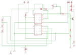
Well I have not tried you circuit yet because I don't have the supplies for that. I don't have a 556 one of the pins broke (working on fixing that) but i have done as suggested and put a 10k resistor from the 9v supply and then from the output on one 555 to the reset of the other 555. The problem is the kHz of my infrared led's is in the 100's range when I have found that the kHz of my remote is 39 kHz. First my remote jammer schematic looks like this.

TV-RemoteJammer.gif

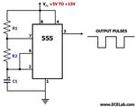
And my Multi-Vibrator (MV) Looks like this

circuit-astable-555.jpg

For C1 I am using a 0.01 uF capacitor
For R1 I am using a 10k resistor
For R2 I am using two 33k resistors to make 66k
and a 9v power supply
 

try this thing ....this link will get u out from 555....first practise on transistor based circuit then go toward ics........
IR Remote Control Jammer

hope it helps....

Thanks I will try it out when I get the supplies.

---------- Post added at 17:02 ---------- Previous post was at 16:40 ----------

but I would still be happy to get this one done. any ideas?
 

Well I have not tried you circuit yet because I don't have the supplies for that. I don't have a 556 one of the pins broke (working on fixing that) but i have done as suggested and put a 10k resistor from the 9v supply and then from the output on one 555 to the reset of the other 555. The problem is the kHz of my infrared led's is in the 100's range when I have found that the kHz of my remote is 39 kHz. First my remote jammer schematic looks like this.

View attachment 61146

And my Multi-Vibrator (MV) Looks like this

View attachment 61147

For C1 I am using a 0.01 uF capacitor
For R1 I am using a 10k resistor
For R2 I am using two 33k resistors to make 66k
and a 9v power supply

There is something seriously wrong. Do you have the datasheet for the version of 555 that you are using? In that datasheet you will find a formula for calculating the frequency, f = 1.44/(Ra+2Rb)C, which in your case should be f = 1.44/(R1+2R2)C.

If my arithmetic is right, that is about 1KHz. Yet, you are seeing 100 KHz? How are you measuring it? Most important, how did you calculate those values to get 39 KHz?

Can you post exactly the schematic you are using. Bits and pieces of other schematics can get quite confusing. Are you talking about the carrier frequency or the modulation frequency?

John

I think my multimeter is ranging it wrong not sure though. I will post a schematic as soon as finished
 

Check your connection for IC1, pin7. Where are the timing components for that oscillator?

Also, although a capacitor from the CV to ground is often not necessary, since you are having strange problems, I would suggest a 0.01 uF capacitor to ground. You can remove it later.

John
 

I'm not sure what you mean by timing components? Do you mean the two resistors and the capacitor?
 

Oh the schematic i used didn't show me where to put it.
TV-RemoteJammer.gif
 

But other schematics showed me to put it between the 1k resistor and the 10k potentiometer. Is this right?
 

Check your connection for IC1, pin7. Where are the timing components for that oscillator?
It's a well known 50% duty cycle circuit and supposed to work.
 
So I should connect DISCHARGE between the 1k resistor and the 10k pot?
 

It's a well known 50% duty cycle circuit and supposed to work.

So are the other standard circuits presented in this thread. Why is it not working?

The variation with DIS not connected and power from the output to charge the timing components is well known. Some suggest that it works with the CMOS version only, but Paisley (**broken link removed**) implies it works with both versions, but not well. I have never come across that version used with an output design like is being used here, but my experience is quite limited. Frankly, I have not had the time nor tried to analyse it carefully.

My point was that with all of the other problems Sneitzke38 is having, now is not the time to introduce a new configuration into an otherwise conservative design. I think he would be far better served sticking with the same conventional design for both oscillators in this circuit (obviously with different timing component values).

I suggest he return to a single, well established configuration of oscillator, get the two frequencies he needs (38-to-39 KHz and 1 KHz) working, then connect them so that the 1KHz oscillator modulates the output of the 38-to-39 KHz oscillator. Certainly, calculating the component values needed for each frequency for the "datasheet" configuration is clear cut.

John

Edit: Removed reference to Horowitz and Hill. Different author.
 
Last edited:
do u use any simulator like protious...?? its better to experiment there first if things going right there then try in real time producing a 38Khz frequency is not a difficult task if you read datasheet properly...... sir FVM and sir jpanhalt are the most experienced person here for you and guiding you toward formulas to calulate the values of resistance and capacitor ....you can use online calulator to calulate thies values if i free soon i will give protious files of 555 based 38khz frequency generator...........

---------- Post added at 20:43 ---------- Previous post was at 20:35 ----------

555 Timer Oscillator Frequency Calculator
use the above link just enter the frequency and get the components values...


---------- Post added at 20:51 ---------- Previous post was at 20:43 ----------

which instrument are you using ..?? i have a problem with measuring instrument when its bettery is low ...when i measure any volatge level with low bettery instrument it add +2 volt in all reading..may be this is the problem with your measuring instrument.....
 

Status
Not open for further replies.

Similar threads

Part and Inventory Search

Welcome to EDABoard.com

Sponsor

Back
Top