Continue to Site

Welcome to EDAboard.com

Welcome to our site! EDAboard.com is an international Electronics Discussion Forum focused on EDA software, circuits, schematics, books, theory, papers, asic, pld, 8051, DSP, Network, RF, Analog Design, PCB, Service Manuals... and a whole lot more! To participate you need to register. Registration is free. Click here to register now.

IR Jammer Circuit not working

Status
Not open for further replies.
just change your 555 it may b burnet......

---------- Post added at 07:41 ---------- Previous post was at 07:23 ----------

final solution of your problem try this circuit ...

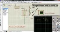
Are there any alternate values? I don't have a 0.0001uF ceramic
 

I'm sorry I am sort of confused. In the calculator you provided it shows OUTPUT going to TRIGGER on a second 555 would I need to wire two of these as shown in your schematic. Or would OUTPUT go to the Infrared LED?

Thanks

---------- Post added at 00:26 ---------- Previous post was at 00:18 ----------

So I am looking for 37000Hz or 37kHz?
 

Hi Ali,
It is the same thing. 38KHz=38,000Hz
 

Alright so i eventually got it working thanks to aliraza786. But it only works for a couple of inches are there any ways to greatly increase the range of it, across the room. Thanks guys
 

if your are desiging a remote controle system in which you have to make reciver and transmiter both then there are ways to increse the range but in your case you have only transmiter....so you can use only one method to increase range is to use more leds .....at output.....use bc337 or anyother common transistor attach the base of transistor to the 3rd pin of 555...emitter to ground.....and anode of leds to battery +ve terminal with suitble resistance..and cathode of led to the collector of the transistor...use almost 3 to 5 ir leds...also use some resistance in kilo ohm at the base...but even then you have to point your jammer toward the tv .you cant controle from other room...ir system need direct link...but it is sure range will increae from inches to some meters
 

Ok if i understood your instructions correctly I hooked up the negative side of the second LED, out of two, to the 4.5v power supply with a 47ohm resistor. Then the output of the 555 is hooked up the the base of the 2N3904 with a 16k resistor. The collector is hooked up to the positive side of the first LED. The emitter is connected to ground. With this setup my 555 gets very hot. Any ideas.
 

It doesn't increase the range of it either
 

Status
Not open for further replies.

Similar threads

Part and Inventory Search

Welcome to EDABoard.com

Sponsor

Back
Top