Continue to Site

Welcome to EDAboard.com

Welcome to our site! EDAboard.com is an international Electronics Discussion Forum focused on EDA software, circuits, schematics, books, theory, papers, asic, pld, 8051, DSP, Network, RF, Analog Design, PCB, Service Manuals... and a whole lot more! To participate you need to register. Registration is free. Click here to register now.

Inverting a pulse signal via 741 op amp

Status
Not open for further replies.

johnfin

Newbie level 6
Joined
Feb 13, 2007
Messages
14
Helped
0
Reputation
0
Reaction score
0
Trophy points
1,281
Activity points
1,390
I need to invert a pulse signal. I tried using a 741 op amp, I connected + and - to Vc+ and Vc-, ground to non-invert pin, original sig to invert pin, output on pin 6. It inverted to negative BUT the signal is not pulsed inverted. Where did I go wrong or do I need to add components?
 

Are you using the op-amps as signal followers (gain of 1) ?
 

Using 741 is not difficult, but for the purpose of inverting the signal, why do you not use the emitter-common circuit using a BJT??? It is much easier to build, cheaper and easy to adjust.

nguyennam
 

To use an opamp as an inverter (gain -1) you need to add at least two resistors (of equal resistance) around it .. see attached picture ..
Otherwise: BJT (or MOSFET) inverter: **broken link removed**

Regards,
IanP
 

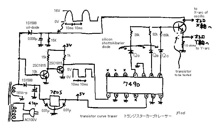
Yes I need a gain of 1. I did use r2/r1(same resistors) but for some reason it did not work and smoked my device and 741. I need to inverse the base signal to the D.U.T. so that I can test pnp's on this curve tracer. Is pin 3 of the op amp voltage gnd for the + and - voltages? Not sure what needs to be done to the DUT for emitter and collecter, flip them?

69_1171459576.gif
 

By the way, why do I want to add resistance to the signal, would that not change the properties of the signal.
 

Changing form NPN to PNP configuration may not be that simple ..

First, you will need to switch reference from 0V to +5V and connect 10Ω resistor from +5V to PNP's emitter ..
Next, generate (negative) 10ms pulses for PNP's collector .. and so on, and so on ..

BTW, what supply voltages do you use for the 741 opamp?

Regards,
IanP
 

IanP, I used 9 vdc + and - for the op amp. Put a diode and a cap off of the 16vac secondary to get + and -. Ok, I can get the negative pulses to collector from the neg. diode, no prob. Neg. base signal via the op amp. And +5 to emitter BUT how do I change the voltage reference without messing everything else or do you mean just run 5vdc to the emitter of the DUT.

Added after 3 hours 59 minutes:

On the op-amp, since the output is in uA( around 80), and say the volts are 9vdc should my 2 resistors on the op-amp be 112K. ie volts/current
 

Status
Not open for further replies.

Part and Inventory Search

Welcome to EDABoard.com

Sponsor

Back
Top