Continue to Site

Welcome to EDAboard.com

Welcome to our site! EDAboard.com is an international Electronics Discussion Forum focused on EDA software, circuits, schematics, books, theory, papers, asic, pld, 8051, DSP, Network, RF, Analog Design, PCB, Service Manuals... and a whole lot more! To participate you need to register. Registration is free. Click here to register now.

Inverter problem

Status
Not open for further replies.

almothanna

Newbie level 5
Joined
Nov 23, 2021
Messages
9
Helped
0
Reputation
0
Reaction score
0
Trophy points
1
Activity points
47
How are you
My 3KVA inverter is pure sine wave showing error 55 which means high DC voltage in AC output or unbalanced voltage
what would be the problem!!?
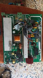
IMG_20211008_133645.jpg
View attachment IMG_20210907_152524.jpg
 
Last edited by a moderator:
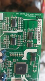
You need to give at least more parameters , make, model, model number, input, output voltage etc.
Then one can try to find a schematic.
Do you have any knowledge in electronics, at least a simple multimeter and a soldering iron ?
 
You need to give at least more parameters , make, model, model number, input, output voltage etc.
Then one can try to find a schematic.
Do you have any knowledge in electronics, at least a simple multimeter and a soldering iron ?
Made in china inverter brand is OREX 3KVA maximum PV voltage is 145V 60A mppt, Yes I have knowledge in electronics and I have electric toolsIMG_20210907_153534.jpg
 
Last edited by a moderator:

With small load there are no problem at all but when I try to load some additional load just like refrigerator the error 55 appear within 10 seconds
 

Likely suspect is a component which rapidly switches power On-and-Off. Try running the unit at slight load, while you touch your finger to transistors and mosfets.

If you feel one get hot then it might be damaged. Since it's at low power the alarm does not detect overmuch heat or unbalanced volt output.

Do not start removing components until after you've performed numerous tests and diagnosed as much as you can.

refrigerator the error 55 appear within 10 seconds

Refrigerators typically contain a motor which draws surge current at power-up. It might be 2 to 8 times normal running Amperes. Can you determine whether the refrigerator runs normally in 10 seconds, or does it labor as though the inverter lacks power to spin the motor?

Does your meter indicate the DC component appears suddenly, or gradually, at the AC output?
 

Likely suspect is a component which rapidly switches power On-and-Off. Try running the unit at slight load, while you touch your finger to transistors and mosfets.

If you feel one get hot then it might be damaged. Since it's at low power the alarm does not detect overmuch heat or unbalanced volt output.

Do not start removing components until after you've performed numerous tests and diagnosed as much as you can.


Refrigerators typically contain a motor which draws surge current at power-up. It might be 2 to 8 times normal running Amperes. Can you determine whether the refrigerator runs normally in 10 seconds, or does it labor as though the inverter lacks power to spin the motor?

Does your meter indicate the DC component appears suddenly, or gradually, at the AC output?
the problem not in the refrigerator it self, because i tried many types of load, the problem not in the load type but in load volume, regarding the error 55 means is over dc voltage in ac output! which means the wave is deformed, the question is why the wave is been pure sine wave with small load but it would be deformed with big load?
 

Hi,

a scope could show what really happens.
Is there DC, is the waveform distorted, both halfwaves or just one?
...or maybe there is no output error at all, just a problem in the sensing circuit...

Klaus
 

Hi,

a scope could show what really happens.
Is there DC, is the waveform distorted, both halfwaves or just one?
...or maybe there is no output error at all, just a problem in the sensing circuit...

Klaus
I have checked the wave shape by a scope, without load the wave is pure sine wave but when I load it more than 500W the wave become distorted..
 

There ought to be DC feedback to balance the output. Imbalance implies a fault in one of the driver circuits is imbalanced beyond regulator control.
your comment is exactly the same the vendor reply when I asked them about the meaning of error 55 description (over DC voltage in AC output) they said: Check the BUS synchronous rectification MOS and related the drive circuit!! can you help me how to check this circuit!? if you need any pictures from the inverter board, tell me I will send you
 

your comment is exactly the same the vendor reply when I asked them about the meaning of error 55 description (over DC voltage in AC output) they said: Check the BUS synchronous rectification MOS and related the drive circuit!! can you help me how to check this circuit!? if you need any pictures from the inverter board, tell me I will send you
That's a good idea to post all the details and board schematics , my crystal ball is fuzzy.
 

Reduced picture filesize from 15267 kBytes to 88 kBytes. (0.6%)
Still everything essential is visible.
Edaboard is a worldwide forum ... and there are regions with low internet bandwidth.
So please take care not no upload uneccesary huge files

IMG_20211007_160638s.jpg


Klaus
 

synchronous rectification MOS and related the drive circuit!!

Synchronous operation is the name when mosfets (not diodes) perform switching of heavy current. A diode has unavoidable voltage drop which increases as current rises. OTOH mosfets can be driven so they cause less voltage drop and less power loss than diodes.

Timing is critical when to turn each device On-and-Off. The drive circuit must be 'smart'. It needs to sense how to adjust gate timing in order to optimize performance from one second to the next.

(Asynchronous operation uses diodes during part of the switching cycle, making design easier and simpler.)

It's likely one of your mosfets had its operating characteristics altered. Maybe it didn't fail entirely, but it might stay partially On, or never turn entirely On, etc. Or maybe two or more devices misbehave.

Testing of each mosfet is called for. However your board appears to have no gang of mosfets in any of your photos. I see heat sinks which could have components hiding under them. Gaining access will not be easy.

This reply is only my surmise of course.
You can indicate to any element, so I will send you clear photo of them, some of the MOSFETS has been tested or totally changed!! But I didn't get any positive results until now
 

Status
Not open for further replies.

Similar threads

Part and Inventory Search

Welcome to EDABoard.com

Sponsor

Back
Top