himadri117
Newbie level 5

- Joined
- Sep 30, 2009
- Messages
- 9
- Helped
- 0
- Reputation
- 0
- Reaction score
- 0
- Trophy points
- 1,281
- Location
- Kolkata
- Activity points
- 1,377
0 down vote favorite
I am using ADC122S625 (Datasheet: https://www.ti.com/lit/ds/symlink/adc122s625.pdf).
The ADC has a differential input per channel. My signal is from a RF devide with 3V peak to peak and 1.5V DC offset. I want to use the ADC in Single-Ended Input Operation. So I have choosen a Reference Voltage of 1.5V. Now my question is what should I use for the Inverted ADC input?
First I thought I will pull it to Ground as a normal Single input ADC would use 0 to Va input range. But after reading the Datasheet (page. 15) it seems that I need to feed the Vref (1.5V) to the inverted inputs.
From Datasheet (copied)::
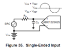
"Single-Ended Input Operation For single-ended operation, the non-inverting inputs of the ADC122S625 can be driven with a signal that has a maximum to minimum value range that is equal to or less than twice the reference voltage. The inverting inputs should be biased at a stable voltage that is halfway between these maximum and minimum values. In order to utilize the entire dynamic range of the ADC122S625, the reference voltage is limited at VA / 2. This allows the non-inverting inputs the maximum swing range of ground to VA. Figure 35 shows the ADC122S625 being driven by a full-scale single-ended source. Even though the design of the ADC122S625 is optimized for a differential input, there is very little performance degradation while operating the ADC122S625 in single-ended fashion."

Please suggest to clear my understanding about the Inverted input.
I am using ADC122S625 (Datasheet: https://www.ti.com/lit/ds/symlink/adc122s625.pdf).
The ADC has a differential input per channel. My signal is from a RF devide with 3V peak to peak and 1.5V DC offset. I want to use the ADC in Single-Ended Input Operation. So I have choosen a Reference Voltage of 1.5V. Now my question is what should I use for the Inverted ADC input?
First I thought I will pull it to Ground as a normal Single input ADC would use 0 to Va input range. But after reading the Datasheet (page. 15) it seems that I need to feed the Vref (1.5V) to the inverted inputs.
From Datasheet (copied)::
"Single-Ended Input Operation For single-ended operation, the non-inverting inputs of the ADC122S625 can be driven with a signal that has a maximum to minimum value range that is equal to or less than twice the reference voltage. The inverting inputs should be biased at a stable voltage that is halfway between these maximum and minimum values. In order to utilize the entire dynamic range of the ADC122S625, the reference voltage is limited at VA / 2. This allows the non-inverting inputs the maximum swing range of ground to VA. Figure 35 shows the ADC122S625 being driven by a full-scale single-ended source. Even though the design of the ADC122S625 is optimized for a differential input, there is very little performance degradation while operating the ADC122S625 in single-ended fashion."

Please suggest to clear my understanding about the Inverted input.
