Continue to Site

Welcome to EDAboard.com

Welcome to our site! EDAboard.com is an international Electronics Discussion Forum focused on EDA software, circuits, schematics, books, theory, papers, asic, pld, 8051, DSP, Network, RF, Analog Design, PCB, Service Manuals... and a whole lot more! To participate you need to register. Registration is free. Click here to register now.

Interleaved boost converter digital control

Status
Not open for further replies.

elecTomas

Junior Member level 2
Joined
Feb 18, 2015
Messages
21
Helped
1
Reputation
2
Reaction score
1
Trophy points
3
Activity points
202
Dear all,

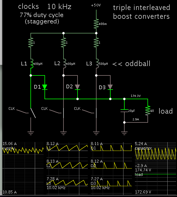
I am designing the control loop of a 3 stages interleaved boost converter already built and operating. However, the inner current loop gives a current value which is two times what I expect. The small-signal model and transfer functions are correct, they have been checked several times by different people already and also compared with other papers and researches. Let me briefly explain the design of the model.

converterControl.png

There are three inner loops for the current control, one loop for each inductor, where the reference is the input current divided by three. Gid is the control-to-inductor current transfer function. The outer loop corresponds to the voltage control, Gvi is the input current-to-output voltage transfer function. The output voltage follows perfectly the reference, but the current is two times what I expect, exactly two times.

I have also tried by simplifying the model to single-stage boost converter, and the result is exactly the same. And as I have said, the transfer functions are correctly calculated.

Thanks a lot for your help.
 

Where do you see doubled current, in which situation? In steady state, the inner loop current setpoint must be obviously equal to output current, are you talking about transient states?
 

I think it will work better if you set the same duty cycle for all the converters. Stagger the timing cycles 120 degrees apart. Any time you adjust the duty cycle, apply it to all the converters.

Reason: From your description, you believe each inductor should carry equal current, so you have each converter operating independently of the other two. However when you make a change in one converter, it affects action in another converter. The control modules will tend to 'jostle about', and your output will be less-than-stable. Or, it will need a long settling time after you make some change.

In case it will help to look at some simulated scope traces, I got out my virtual triple interleaved boost converter. The timing cycles are equal.

I set one inductor to an oddball value (25% high). Notice that inductor carries greater Amperes, but the variation is not as severe as we would be led to expect.

In fact, it is the coil's DC resistance, which is more likely to create differences in behavior.


I think it will work better if you set the same duty cycle for all the converters. Stagger the timing cycles 120 degrees apart. Any time you adjust the duty cycle, apply it to all the converters.

I presume, the design of interest is a synchronous boost converter. Individual current control loops are pretty standard for synchronous converters to assure equal current sharing despite of power stage asymmetries and achieve precise current limiting. 3 x 120° phase shift is already implied by the title "interleaved" boost converter.
 

is 2x gain due to differential gain sensing?


In this case measurement gains have not be taken into account.

- - - Updated - - -

Where do you see doubled current, in which situation? In steady state, the inner loop current setpoint must be obviously equal to output current, are you talking about transient states?

I see it in steady state. The transient and system response behaviour is something I can expect (overshoot, setting time, error...), but in steady state the value is twice what I should have.

I am operating under this conditions: Vin=114V, Vout_ref=600V, Rl=54ohm, D=0.81, Io=11,1, Iin=60A.

But Iin is 120A with the system I presented before...

Your post #1 diagram comes without any signal annotation, so it's unclear where the said values should be assigned. But generally speaking, this sounds like a very basic scaling error. For a specific discussion you should show real models, code, hand calcucations, whatsoever.

Current of internal loop is just internal, so even if you calculated something wrong, what's the actual problem you want to report.
 

I think it will work better if you set the same duty cycle for all the converters. Stagger the timing cycles 120 degrees apart. Any time you adjust the duty cycle, apply it to all the converters.

Reason: From your description, you believe each inductor should carry equal current, so you have each converter operating independently of the other two. However when you make a change in one converter, it affects action in another converter. The control modules will tend to 'jostle about', and your output will be less-than-stable. Or, it will need a long settling time after you make some change.

In case it will help to look at some simulated scope traces, I got out my virtual triple interleaved boost converter. The timing cycles are equal.

I set one inductor to an oddball value (25% high). Notice that inductor carries greater Amperes, but the variation is not as severe as we would be led to expect.

In fact, it is the coil's DC resistance, which is more likely to create differences in behavior.


Hi, thanks for your reply! Sorry for answering so late, but yesterday I wrote a reply but it seems it wasn't sumbitted.

Yes, I thought about waht you say, and I see the problem now. However my converter prototype show some variations greater thant 3A in the rms current at high power. That's why I would like to implement this kind of control, otherwise I will loose precision in the current distribution and for safety reasons I don't want to loose the control of each stage. However, I also need to control the output DC link voltage, so I can't implement a current control loop with current reference.. I also need a control voltage loop...

Any recommendations?
 

Status
Not open for further replies.

Similar threads

Part and Inventory Search

Welcome to EDABoard.com

Sponsor

Back
Top