asking
Full Member level 5
Hi,
I am trying to interface Magnetic Float Sensor (Reed Switches) with PIC16F1847 for water level measurement. When i test circuit on bread board it works great but when i really interface with real world behavior is completely different and not working as per logic.
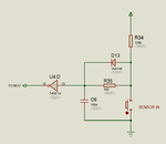
Circuit Schematic given below.

There are 3 switches shown (which means Level Sensor Reed Switch Contact in water). Logic is very simple when all the 3 switches read 0 0 0 motor starts and when all the 3 level switches read 1 1 1 motor is stopped. Logic works great within breadboard. But i interface with simple signal cables around 3-40 meters long. when any 2 sensors are switched on motor starts and logic is changed completely. I simulated the logic and logic is perfect.
The Help i need from you guyz:
your suggestions for taking input from reed switches contact. Do i need to take them first to base of transistor and then give output of transistor to microcontroller ? Because directly reed switch contact is not reliable with long cables around 3-40 meteres (tested already).
So please throw some light.
My alternate options : (Please verify)
What i think is due to direct 5V output to microcontroller is really unreliable. Better i should used Bufffered output to microcontroller ?
So i am thinking to put some buffer in between to boost the weak signal from long lengthy wires....

So am i right ? or something else i should use ?
I am trying to interface Magnetic Float Sensor (Reed Switches) with PIC16F1847 for water level measurement. When i test circuit on bread board it works great but when i really interface with real world behavior is completely different and not working as per logic.
Circuit Schematic given below.
There are 3 switches shown (which means Level Sensor Reed Switch Contact in water). Logic is very simple when all the 3 switches read 0 0 0 motor starts and when all the 3 level switches read 1 1 1 motor is stopped. Logic works great within breadboard. But i interface with simple signal cables around 3-40 meters long. when any 2 sensors are switched on motor starts and logic is changed completely. I simulated the logic and logic is perfect.
The Help i need from you guyz:
your suggestions for taking input from reed switches contact. Do i need to take them first to base of transistor and then give output of transistor to microcontroller ? Because directly reed switch contact is not reliable with long cables around 3-40 meteres (tested already).
So please throw some light.
My alternate options : (Please verify)
What i think is due to direct 5V output to microcontroller is really unreliable. Better i should used Bufffered output to microcontroller ?
So i am thinking to put some buffer in between to boost the weak signal from long lengthy wires....
So am i right ? or something else i should use ?