Continue to Site

Welcome to EDAboard.com

Welcome to our site! EDAboard.com is an international Electronics Discussion Forum focused on EDA software, circuits, schematics, books, theory, papers, asic, pld, 8051, DSP, Network, RF, Analog Design, PCB, Service Manuals... and a whole lot more! To participate you need to register. Registration is free. Click here to register now.

[PIC] Interfacing Magnetic Float Sensor to PIC16F1827! Issue

Status
Not open for further replies.

asking

Full Member level 5
Joined
Sep 21, 2010
Messages
279
Helped
6
Reputation
12
Reaction score
6
Trophy points
1,298
Activity points
3,377
Hi,

I am trying to interface Magnetic Float Sensor (Reed Switches) with PIC16F1847 for water level measurement. When i test circuit on bread board it works great but when i really interface with real world behavior is completely different and not working as per logic.

Circuit Schematic given below.
24mgcbn.png


There are 3 switches shown (which means Level Sensor Reed Switch Contact in water). Logic is very simple when all the 3 switches read 0 0 0 motor starts and when all the 3 level switches read 1 1 1 motor is stopped. Logic works great within breadboard. But i interface with simple signal cables around 3-40 meters long. when any 2 sensors are switched on motor starts and logic is changed completely. I simulated the logic and logic is perfect.


The Help i need from you guyz:
your suggestions for taking input from reed switches contact. Do i need to take them first to base of transistor and then give output of transistor to microcontroller ? Because directly reed switch contact is not reliable with long cables around 3-40 meteres (tested already).

So please throw some light.

My alternate options : (Please verify)
What i think is due to direct 5V output to microcontroller is really unreliable. Better i should used Bufffered output to microcontroller ?

So i am thinking to put some buffer in between to boost the weak signal from long lengthy wires....

2v86e5e.png


So am i right ? or something else i should use ?
 

Zip and post Proteus file. How does the float switches work that is explain how the 3 sensors (sump low, ohh and ohl) work, like...

sump low sensor (NO when sufficient water, NC when low level of water)
ohh low sensor (NO when sufficient water, NC when low level of water)
ohl low sensor (NO when sufficient water, NC when low level of water)


Edit:
 
Last edited:

Float Sensors are Having contact when immersed in water and Normally open when no water. Explanation is very simple. Normally when there is no water the Input port of the MCU gets 0 (all used input ports are pull down). When sensor makes contact i.e when water is available all input port connected reads Logic 1 (5V) input.
 

Do you have a datasheet on your float sensor ?
if it is like a reed switch you must have in front a magnet , isn't it ?
and the contact change only in a few delta level..

If it is dry contact (like reed switch) you can increase the current value to 50mA
with R1,R2,R3 =100 ohms
 
  • Like
Reactions: asking

    asking

    Points: 2
    Helpful Answer Positive Rating
Its purely as Reed Switch capable of driving 1AMP Current. But long wire make something going to be wrong which gives weired output results..... You mean to say i should pull down to ground using 100OHM resistor ? Wont be that very hot when contact is on ? (reed switch on) it would heat up unnecessarily and cause power loss...
 

You have three sensors and so 8 possible conditions. Two are 000 and 111 what happens for other 6 conditions?
 
  • Like
Reactions: asking

    asking

    Points: 2
    Helpful Answer Positive Rating
Doing nothing for other 6 conditions remain off. Although i have consider some Fault conditions but not implemented them right now until i solve this one.
 

Wont be that very hot when contact is on ?

Maximum power disspation : U* U /R => 5*5/100 = 0.25W per resistor
What is the section of the wire inside the cable .. to know how mV or volt you loose with 50mA...and 40 meter long.

Consumption 3x50mA=> 150mA could be a problem if your power supply is a battery
if main power from AC 230V .. boof
In industrial environnment , With very low current as 5mA in dry contact we ofen use Gold or Silver contact.
 

This system is for home based system and with power saving features. So implementing such would loose few watts until its on. And in most cases tank would be full so atleast 1 or 2 sensors continously loosing some energy in form of heat. How about my idea by using buffer driver circuit as i suggested ? totem pole type ? will it help ? i think by using that buffer circuit i do not need to pull down the input....
 

Then why don't you use 3 input AND gate? Why do you need MCU for that? The 3 input AND gate will do the work. Use a transistor at o/p of AND gate. When condition is 111 then AND out is 1 and transistor turns ON the relay. For other conditions AND out is 0 and relay will be OFF.
 
  • Like
Reactions: asking

    asking

    Points: 2
    Helpful Answer Positive Rating
Then why don't you use 3 input AND gate? Why do you need MCU for that? The 3 input AND gate will do the work. Use a transistor at o/p of AND gate. When condition is 111 then AND out is 1 and transistor turns ON the relay. For other conditions AND out is 0 and relay will be OFF.

you're right. But there are other conditions too like safety timer, and many other interlocks. So doing hard wiring is boring job. That why i used MCU.
 

Ok. Zip and post Proteus file (.DSN / .psdprj / PDF) and code (project files).
 

...So am i right ? or something else i should use ?[/FONT][/COLOR]

it is seldom that we would use a pull-down resistor for a TTL input. You should simply invert your logic and put the 1K resistors as pull-upsto +5v instead. This itself will help with your noise problem.
 

Don't use Transistors. It will pick up the noise when your cables are too long. I have faced that problem earlier.
Either you can use, pull up resistor. Connect the sensor directly with the micro-controller and use the pull up resistor.

I'm sure it works perfectly. I have tested it already.

Connections:
One end of sensor to ground. Other end to uC pin. connect 10K pull up to that pin.

Best wishes.
 

Better use 2 flow sensors which give pulse output. One connected to sump pump and another to overhead tank drain. The flow sensors give pulses per amount of fluid flow like 60 pulse per liter. If you don't get pulse even after 2 sec after switching the motor then it means sump is low and this condition will turn off the pump to avoid dry run. The overhead drain flow sensor is used to count how much water is drained from overhead tank from the pulse count. Initially in setup mode you have to enter L, W, H of overhead tank (OHT) and the system will find out the volume of OHT and save it in eeprom. Then initially (first run) OHT will be empty and if water present in sump then water is pumped to OHT. If you drain water from OHT even while pumping it calculates either water pumped and water drained and pumps till the vol of water required to fill the OHT is pumped (using liter of water pumped - liter of water drained and vol stored in eeprom) and then pump switches off. The condition to start pump is if vol of water in OHT is x (x is the user set level which is the vol of water in OHT whose level is say 2 inches above the drain pipe). x is stored in eeprom initially during setup (if drain out pipe is at 4 inches from OHT bottom and water vol for water level to be 2 inches above drain pipe is 50 liters then 50 is stored in eeprom). If initial vol in OHT and current vol is less than 50 liters then pump starts and if it doesn't detect pulse from sump flow sensor within 2 sec then pump is turned off else pumps.
 

Better use 2 flow sensors which give pulse output.
If you don't manage to ride a bicycle, go be feet?

There may be reasons to use other sensor principles than level sensing, but in a first order, the suggestion is simply off-topic.

I would expect an analysis why the sensors aren't working as expected, e.g. voltage measurements or looking at processor input signals with MPLAB debugger. Reed contacts usually have no problem to switch low currents. But if the problem is picked-up noise as suggested by hemnath, reducing the load- respectively pull-up resistors would help a bit. Placing a RC filter before each pin and/or software debouncing methods seems to me the better solution.

As you also mentioned low-power operation. It's pretty easy to operate the processor in sleep mode with periodical wake-up and activate pull-up resistors only when reading the sensors. This way you can reduce the average current consumption to a few 10 µA.
 

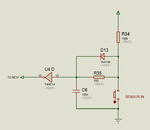
You can also use schmitt Inverter based debounce circuit for the sensors. To reduce board size you can use TinyLogic devices.

105666d1400833605-schmitt-inv.png
 

Attachments

  • schmitt inv.png
    schmitt inv.png
    11.2 KB · Views: 77
Last edited:

Status
Not open for further replies.

Part and Inventory Search

Welcome to EDABoard.com

Sponsor

Back
Top