Continue to Site

Welcome to EDAboard.com

Welcome to our site! EDAboard.com is an international Electronics Discussion Forum focused on EDA software, circuits, schematics, books, theory, papers, asic, pld, 8051, DSP, Network, RF, Analog Design, PCB, Service Manuals... and a whole lot more! To participate you need to register. Registration is free. Click here to register now.

Interface LCD with PIC18f452

Status
Not open for further replies.

Afnan_123_

Newbie level 6
Joined
Feb 19, 2013
Messages
11
Helped
0
Reputation
0
Reaction score
0
Trophy points
1,281
Activity points
1,355
Hello
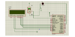
I am working in project to measure the temperature of the room
when i did it in proteus program it's working,
but can anyone check the connection of the pins ?
because i think we should use capacitor and resistor?
if we should use it, where i can connect them in the circuit

View attachment 8714
 

Attachments

  • lcd.png
    lcd.png
    38 KB · Views: 66
Last edited:

when i did it in proteus program it's working,
So its working in proteus and not working in real hardware? In proteus, uC is powered internally. But in real hardware, You have to power it.
LCD pins 1,7,8,9,10 should be grounded. Pin 2 : +5V, pin 3 : 10K pot for contrast adjustment.

follow the link. It might help you
https://embedded-lab.com/blog/?p=4001

- - - Updated - - -

when i did it in proteus program it's working,
So its working in proteus and not working in real hardware? In proteus, uC is powered internally. But in real hardware, You have to power it.
LCD pins 1,7,8,9,10 should be grounded. Pin 2 : +5V, pin 3 : 10K pot for contrast adjustment.

follow the link. It might help you
https://embedded-lab.com/blog/?p=4001
 

2,7,8,9,10 should have a gnd
1 should have a VSS
3 most likely a potentiometer to adjust the contrast of the LCD

now it should be

1,7,8,9,10 should have a gnd
2 should have a VDD
3 most likely a potentiometer to adjust the contrast of the LCD
 
Last edited:

hi mldt28,
How LCD pin 2 should be grounded?
Please read the datasheet of LCD again. Pin 2 should be +5V.
PIN1 must be grounded
 

ai sorry... haha
its the opposite...
1 is grounded..
and 2 is in VDD ^^
thats the ryt one....
 
Last edited:

hi mldt28,
PIN 2 should be VDD. Not VSS.
Mostly, Vss described for Ground reference for logic and I/O pins.
Vdd described for Positive supply for logic and I/O pins.

Be clear while helping others.
 

thank u for ur answers

i understood what u r said
previous i was confuse about the pins of lcd how to connect it
so no need to connect capacitor for pin 13 and 14 of PIC?
 

Try connecting the contrast pin on the LCD to ground, this is the most common problem with this circuit.
 

After powering the assembly, what's happening on the display?
1. LCD lights up. But still nothing displays on the screen?
If it happens, Please tel me whether you are using external or internal oscillator?
If you are using external crystal, make sure the connections to uC from crystal are good. In proteus, even if you don't connect the crystal to uC, it will works. But not in real hardware.

2.LCD lights up. But black boxes on the screen?
In this case, you have adjust the value of the potentiometer which is connected to LCD pin3.

3. LCD does not lights up.
Check the connections.
 

Status
Not open for further replies.

Similar threads

Part and Inventory Search

Welcome to EDABoard.com

Sponsor

Back
Top