Welcome to our site! EDAboard.com is an international Electronics Discussion Forum focused on EDA software, circuits, schematics, books, theory, papers, asic, pld, 8051, DSP, Network, RF, Analog Design, PCB, Service Manuals... and a whole lot more! To participate you need to register. Registration is free. Click here to register now.
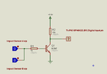
He is interfacing 2 crash (impact) sensors to PIC18F46K22. I told him to use one external interrupt pin to interface both sensors instead of using 2 ext int pins. That is why he is using 2 input OR gate between sensors outputs and MCUs INT0 pin.
He is interfacing 2 crash (impact) sensors to PIC18F46K22. I told him to use one external interrupt pin to interface both sensors instead of using 2 ext int pins. That is why he is using 2 input OR gate between sensors outputs and MCUs INT0 pin.
I told him to use only one ext int pin (INT0) so that INT1 and INT2 can be used for other purposes. Only one crash sensor is needed but he thinks if is better and safe to use 2 crash sensors in parallel so that if one of them fails then also his system will work. I told him to use OR gate to interface both sensors to INT0 pin.
I told him to use only one ext int pin (INT0) so that INT1 and INT2 can be used for other purposes. Only one crash sensor is needed but he thinks if is better and safe to use 2 crash sensors in parallel so that if one of them fails then also his system will work. I told him to use OR gate to interface both sensors to INT0 pin.
Yes, can see your point about leaving spare interrupt pins.
Though if he wants to use 2 crash sensors, my choice would be to avoid using extra logic chips in the design when the micro has that ability; he seems to have plenty of spare pins and there is also the 4 pins Rb4-7 with the Interrupt on Change feature he can utilize.
This site uses cookies to help personalise content, tailor your experience and to keep you logged in if you register.
By continuing to use this site, you are consenting to our use of cookies.