Dublimax
Newbie level 2

- Joined
- Sep 3, 2013
- Messages
- 2
- Helped
- 0
- Reputation
- 0
- Reaction score
- 0
- Trophy points
- 1
- Activity points
- 25
I want to be able to open the gate of the gated car parking where I live as I lost the swap card. I can open it for visitors from my apartment by answering the intercom and pressing a button. I want to be able to dial my apartment number to open the gate without anyone in my apartment.
I opened my intercom handset. See pictures attached.
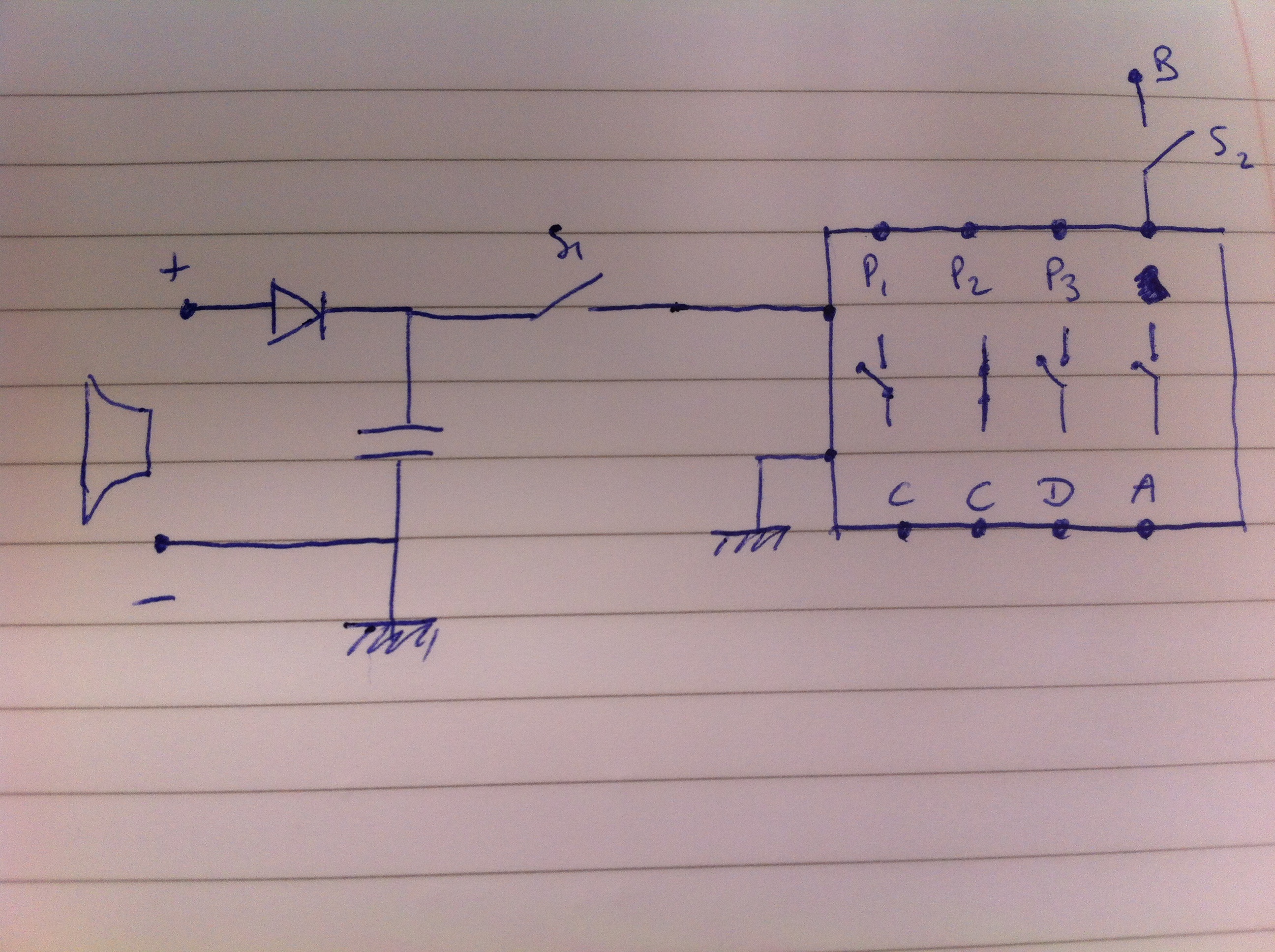
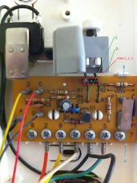
To open the gate when someone buzzes I have to hang on which makes C and D go from D connected to nothing and C connected to pin 2 to C connected to 1 and D connected to 3(how they are on the picture). Once I have hanged on I press a button which pushes A on the right hand side of the picture 2, that makes connection with B.
I am a mechanical engineer and very bad at electronics but here is my idea:
My idea was to take the signal from the microphone (AC signal I guess), convert it to a a DC signal with a diode and a condenser (no idea about the values). This signal could activate a little solid state relay that would connect C and D to pins 1 and 3 to simulate that someone hanged on. The solid state would also connect D to B.
The problem I see by doing it this way is that C would still be connected to pin 2 whereas it shouldn't (is that a problem?).
I also have no clue about what condenser, diode to use and if I need any other components. Or even if my idea is good.
I would appreciate any help.
Thanks
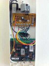
I opened my intercom handset. See pictures attached.
To open the gate when someone buzzes I have to hang on which makes C and D go from D connected to nothing and C connected to pin 2 to C connected to 1 and D connected to 3(how they are on the picture). Once I have hanged on I press a button which pushes A on the right hand side of the picture 2, that makes connection with B.
I am a mechanical engineer and very bad at electronics but here is my idea:
My idea was to take the signal from the microphone (AC signal I guess), convert it to a a DC signal with a diode and a condenser (no idea about the values). This signal could activate a little solid state relay that would connect C and D to pins 1 and 3 to simulate that someone hanged on. The solid state would also connect D to B.
The problem I see by doing it this way is that C would still be connected to pin 2 whereas it shouldn't (is that a problem?).
I also have no clue about what condenser, diode to use and if I need any other components. Or even if my idea is good.
I would appreciate any help.
Thanks