Follow along with the video below to see how to install our site as a web app on your home screen.
Note: This feature may not be available in some browsers.
Two possibilities come to mind:
1) Solder wires to existing led connections and have them connect to a buffer amplifier with high input impedance, to drive external led.
2) Mount a CdS photocell next to each led, in a light-tight enclosure, and use the resistance change to trigger the external led circuit. But CdS cells might have speed issues. So maybe use a photodiode or other opto device, instead, depending on your application's requirements.

Hi, after many hours testing (+) IC Pins and (-) 8 contacts on botton of circuit (same that connect RJ45 port), it worked, then i soldered 16 wires direct on pcb then soldered on external led, all work with red leds (2.0v-2.2v), but when i try use green leds (3.0v-3.2v), only 1 of 8 led ouptuts work, then i measured voltage using multimeter on each led ouptut, first one (that worked with green led) was 2.78v and all another ones was only 1.93v, because of this green leds not worked on anothers ouptuts..EDIT: I couldn't find any specs on the SAM8118 IC that is driving your LEDS. But IF, and ONLY IF, that IC could safely supply enough current, you could POSSIBLY use only a series resistor and LED, for the external circuit for each LED, INSTEAD of something like the circuit I posted below. In that case, you could just put a current-limiting resistor in series with an external LED, and connect that circuit's leads across an existing LED on the PCB. Very simple.
-----
Should be easy, especially if the PCB's power supply can supply the current for the additional LEDs.
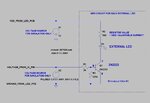
You could solder a wire to each of the IC pins that drives an LED and, depending on the "on" and "off" voltages, run each one through a series resistor and then to the gate or base of a switching transistor. The transistor would be between Vsupply and ground (also from the PCB), with a series resistor and LED somewhere in the path between Vsupply and ground.
I will attach a schematic that might work. I used the 2N7000, which is a small transistor. It needs 3 Volts or more on its gate (worst-case max) to turn on. You can use other transistors. You will need to determine the proper value for the resistor in series with the LED, to limit the current.
View attachment 94691
P.S. If you solder to IC pins, be very careful to not over-heat the IC! Conduct the heat away, maybe like this: Grip the IC pin with a needle-nose pliers, between the IC and where you will solder. A rubber band on the pliers handle could hold it closed for you. If you can find some better place to solder to the PCB, to get the same signals, you should do so.
