Continue to Site

Welcome to EDAboard.com

Welcome to our site! EDAboard.com is an international Electronics Discussion Forum focused on EDA software, circuits, schematics, books, theory, papers, asic, pld, 8051, DSP, Network, RF, Analog Design, PCB, Service Manuals... and a whole lot more! To participate you need to register. Registration is free. Click here to register now.

[SOLVED] Integrate and Dump Simulink model

Status
Not open for further replies.

FuzzySNR

Member level 2
Joined
Oct 3, 2005
Messages
47
Helped
0
Reputation
0
Reaction score
0
Trophy points
1,286
Activity points
1,688
I am unsuccessfully trying to replicate the behavior of the Integrate and Dump block in Simulink (Communication Systems Toolbox).
The problem arises at t=4, where the current counter value=4 should add to the next value=5 resulting to 9.

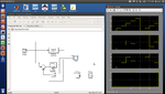
I am attaching a screenshot of the Simulink model along with the Waveform window and a zipped Simulink model for anyone who's willing to help me fix the model.

**broken link removed**
 

Attachments

  • IntegrateAndDump.png
    IntegrateAndDump.png
    138.8 KB · Views: 256
  • IntegrateAndDump.zip
    15.3 KB · Views: 128
Last edited:

the thing is that in t=4 delay line is resetet and it takes new value in t=5 so its output that value in t=6. You should maybe use normal 1/z line and use switch to force 0 to 1 input of adder.
edaboard.png

View attachment IntegrateAndDump.zip
 
Last edited:
Yep, that's it! I feel so dumb I didn't figured it out myself...Excellent, thanks a lot!
 

Status
Not open for further replies.

Part and Inventory Search

Welcome to EDABoard.com

Sponsor

Back
Top