robismyname
Full Member level 6
- Joined
- Jan 17, 2008
- Messages
- 390
- Helped
- 11
- Reputation
- 22
- Reaction score
- 9
- Trophy points
- 1,298
- Location
- Central Florida
- Activity points
- 4,603
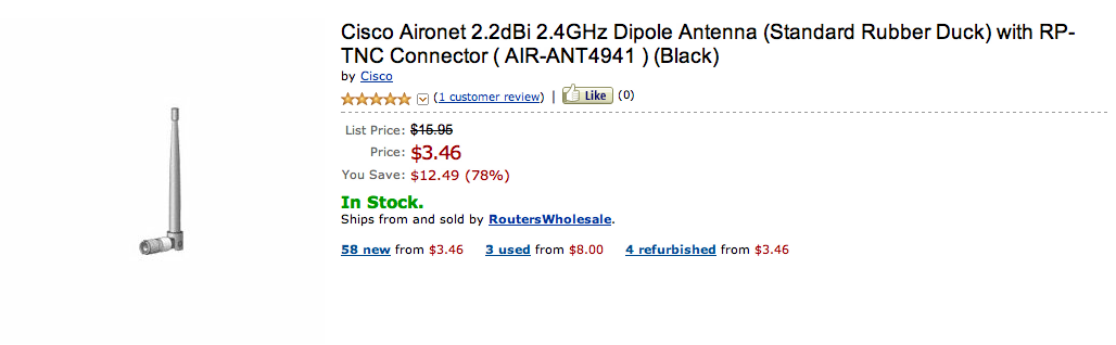
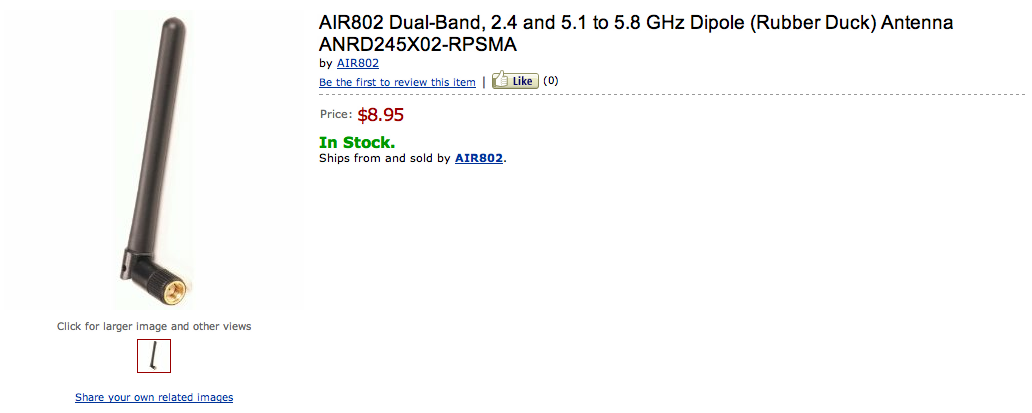
If I were to remove the casing around one of those 2.4Ghz 1/2 wave dipole antennas would I see the attached?
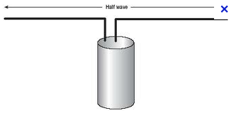
I ask because I removed the casing long time ago and I recall seing just a piece of thin coax, there was not two element as they show in antenna text books and my attached file.
So my question is can you have a dipole 1/2 wave without it looking like the attached design diagram just using a piece of coax?