Continue to Site

Welcome to EDAboard.com

Welcome to our site! EDAboard.com is an international Electronics Discussion Forum focused on EDA software, circuits, schematics, books, theory, papers, asic, pld, 8051, DSP, Network, RF, Analog Design, PCB, Service Manuals... and a whole lot more! To participate you need to register. Registration is free. Click here to register now.

Input to ADC from a voltage divider

Status
Not open for further replies.

kookie91

Newbie level 6
Newbie level 6
Joined
Jan 30, 2013
Messages
13
Helped
0
Reputation
0
Reaction score
0
Trophy points
1,281
Visit site
Activity points
1,368
Hello

I am using a 24bit ADC embedded in a microcontroller board. Vref is 1.2V.
When i used function generator to give input to the adc input pins, the voltage reading in the hyperterminal was correctly shown ( I used 100mV from function generator).
But when I use a voltage divider, the voltage reading in the hyperterminal is not correct.
Can anyone please tell me why is that so?
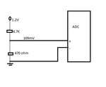
eda.jpg

Thank you
 

"Not correct" is somehow vague. What's the deviation? Is the ADC specified to measure downto zero? What's the required source impedance? Which processor?
 

Instead of showing around 109 mV, it displays about 26 mV.
Im trying to measure the voltage changes of a resistive sensor , whose resistance is about 500 ohms, under a 100mV bias. So when the resistive sensor changes its resistance, the Vout of voltage divider changes and this voltage is what is given to the adc.
The processor is arm cortex m3. And the ADC input range is set between ) 0v to 500 mV.
 

Many converters will impose input charge / current /
kickback-noise on the source and need to be driven
by a low impedance buffer. A differential ADC with
discrepant +. - input impedances will also bend the
at-the-pins voltage away from the ideal divided
source value.

Outfits like ADI make purpose-specific ADC drivers,
because some ADCs need them.
 

Yes, Im using ADI's ADuCM360 board. And it has an option of setting the input buffers on. I tried that. It doesnt seem to work.
Is there anything I can do to avoid this bending of voltage?
I will be dealing with very small voltages here, mV range. So it is essential that I cut back such effects.
 

You did read the ADuCM360 absolute input voltage specification? It's 100 mV in buffered mode, so your measurement probably won't work in this mode.

I can generally confirm that the ADuC analog front end works as specified. Without knowing your exact circuit and ADC configuration, it's hard to say what's wrong in your application.
 

I will try to give the output from voltage divider to the adc via a buffer amplifier. using ADuCM360 on board buffers doesnt seem to work.
 

I overlooked the post #1 circuit in my latest post, although I had seen it before.

According to datasheet, 109 mV should be within the buffer voltage range, but I the 0.1V margin specification possibly isn't very exact. The circuit should however work in unbuffered mode (at least for test). If it doesn't, annother yet recognized problem can be expected.
 

Status
Not open for further replies.

Part and Inventory Search

Welcome to EDABoard.com

Sponsor

Back
Top