Continue to Site

Welcome to EDAboard.com

Welcome to our site! EDAboard.com is an international Electronics Discussion Forum focused on EDA software, circuits, schematics, books, theory, papers, asic, pld, 8051, DSP, Network, RF, Analog Design, PCB, Service Manuals... and a whole lot more! To participate you need to register. Registration is free. Click here to register now.

Input impedence to see the effect of Miller effect

Status
Not open for further replies.

vinanalog

Newbie level 1
Joined
Feb 29, 2012
Messages
1
Helped
0
Reputation
0
Reaction score
0
Trophy points
1,281
Activity points
1,287
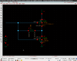
See the schematic attached. Since the amplifier is having a a negative gain at dc, I am expecting the real part of my input impedance as positive,through miller approximation. But cadence simulation gives a negative value for the real part of input resistance(or it gives a phase of 180 degrees at dc) Wy so? schematic_miller.png
 
Last edited:

A single-stage common-source amplifier always has a inverted output (phase of 180 degrees) at DC or low frequencies. That gives a negative (inverted) gain.
 

Status
Not open for further replies.

Part and Inventory Search

Welcome to EDABoard.com

Sponsor

Back
Top