milvapp
Member level 5
- Joined
- Apr 17, 2010
- Messages
- 88
- Helped
- 3
- Reputation
- 6
- Reaction score
- 2
- Trophy points
- 1,288
- Location
- chania greece
- Activity points
- 1,882
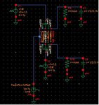
I have designed a single-balanced passive mixer having an ideal current source
as input.After the switches,as seen in Fig.1,there are LPF's with a cut-off
frequency of 10 MHz.I get the expected output however I cannot understand
why when I plot the input gain,its form is like the one shown in Fig.2 .Shouldnt it
be the similar to the LPF? (I run PSS/PAC analysis to get the results).
Fig.1
Fig.2
as input.After the switches,as seen in Fig.1,there are LPF's with a cut-off
frequency of 10 MHz.I get the expected output however I cannot understand
why when I plot the input gain,its form is like the one shown in Fig.2 .Shouldnt it
be the similar to the LPF? (I run PSS/PAC analysis to get the results).
Fig.1

Fig.2
