Continue to Site
Follow along with the video below to see how to install our site as a web app on your home screen.
Note: This feature may not be available in some browsers.

Thank you very much for answers.
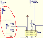
The datasheet says TA31136 input impedance is around 4 KOhm at 21,7 Mhz
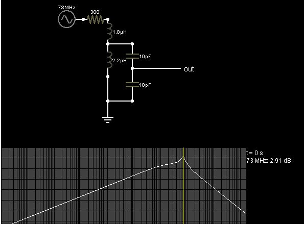
The formula posted below is good?
View attachment 120086
The ratio of L:C is important??
Capacitors C1,C2 are in series or in parallel?