Midisaurus
Newbie level 3

- Joined
- Jun 20, 2014
- Messages
- 3
- Helped
- 0
- Reputation
- 0
- Reaction score
- 0
- Trophy points
- 1
- Activity points
- 30
Hello, I am currently doing some undergraduate research, using SPICE3 to simulate a 9-stage Ring Oscillator in series with an LC tank.
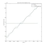
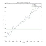
Using a combination of SPICE3's transient analysis and MATLAB, I am attempting to plot the change in oscillation frequency as a function of slight changes in VDD. I have successfully plotted this relation for two circuits: one with and one without the LC Tank.
I was hoping to see some locking range centered around the resonant frequency of the LC tank. However, the LC tank circuit simulation produced a plot nearly identical to the circuit without the tank. (See attached PNGs)
I am using a circuit topology based on a diagram in a paper which claims to have proven a locking range when VDD is adjusted by +/-0.5%. I can attach a rough sketch of my design if needed.
Can anyone suggest what I might change to allow the circuit to lock to the LC resonant frequency at a certain range of VDD?
A few of my suspicions are:
Frequency magnitude (~8GHz)?
The LC Tank should also include a resistance in parallel?
SPICE's numerical analysis/convergence issues. (I have my options set fairly strictly, so I don't want to assume this to be the issue yet.)
Thank you in advance.
- - - Updated - - -
The difference between the two figures is only the VDD range.
With FREQvVDD3, I tried to "zoom in" on a small area of FREQvVDD1 in hopes of seeing some locking at smaller steps of VDD, but no luck.